
Assembling CHRP4
Getting ready
Gather all of the required tools and equipment before assembling CHRP4. We recommend:
a soldering iron with a fine tip for soldering most through-hole parts, as well a flat/blade tip for drag-soldering the USB-C connector pins
electronic solder with a no-clean, or water soluble flux
a flux pen using the same type of flux as your solder for drag-soldering the USB-C connector pins
diagonal cutters or low-profile shear cutters to trim component leads after soldering
small needle-nose pliers to bend component leads before soldering and to hold the nut while securing the voltage regulator screw
a small Phillips screwdriver to secure the voltage regulator screw
You may also want to have the CHRP4 schematic diagram handy for reference to decide which configuration to build and which optional components to install.
Step 1 - Check your components
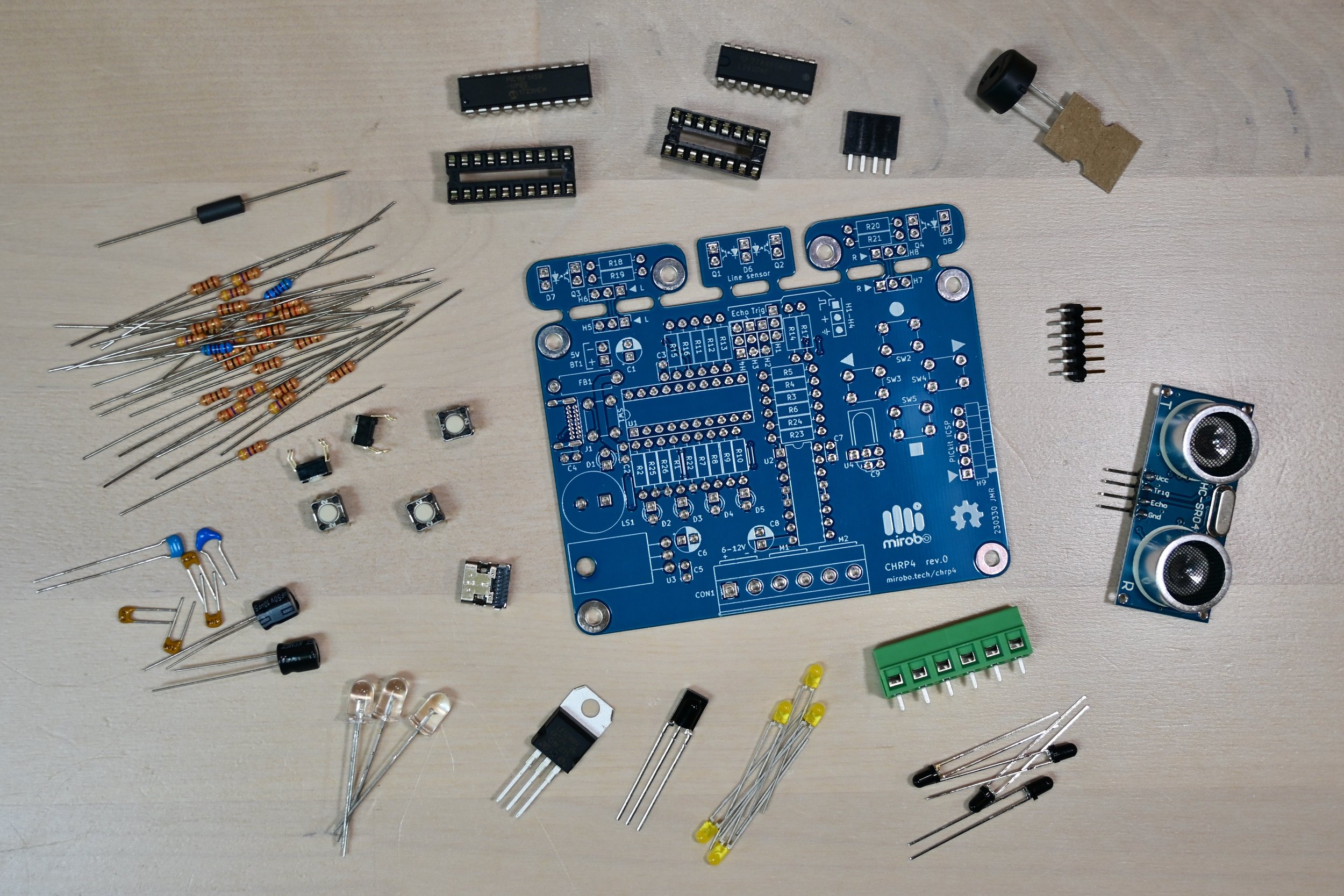
First, confirm that you have all of the required and optional components in your kit.
If you are starting with a bare CHRP4 circuit board instead of a kit and need to obtain the components first, download the more detailed CHRP4 parts list (.csv file) or purchase components from this shared Digi-Key parts list.
Full build top-side components
1 - CHRP4.0 PCB (printed circuit board)
8 - 100Ω, 1/4W resistors (colour code: brown, black, brown, gold)
5 - 470Ω, 1/4W resistors (colour code: yellow, violet, brown, gold)
6 - 1.0kΩ, 1/4W resistors (colour code: brown, black, red, gold)
4 - 4.7kΩ, 1/4W resistor (colour code: yellow, violet, red, gold)
2 - 5.1kΩ, 1% 1/4W resistor (colour code: green, brown, black, brown, brown)
1 - 10kΩ, 1/4 resistor (colour code: brown, black, orange, gold)
1 - USB-C connector
5 - 6mm pushbuttons
1 - 16-pin DIP socket
1 - 20-pin DIP socket
1 - ferrite inductor (un-marked black cylinder)
1 - 1µF ceramic monolithic capacitor (numeric code: 105) or 1µF aluminum electrolytic (polarized)
4 - 100nF ceramic monolithic capacitor (numeric code: 104)
1 - 470nF ceramic monolithic capacitor (numeric code: 474)
2 - 10µF aluminum electrolytic capacitor (polarized)
1 - 12mm piezo beeper (non-polarized)
5 - 3mm LEDs
1 - LF50ABV low-dropout voltage regulator
1 - #4-40 x 0.315” screw
1 - #4-40 nut
2 - 6-pin screw terminal block
1 - SN754410NE (or L293DNE) quad half-H motor driver
1 - PIC16F1459-I/P microcontroller
Bottom-side floor sensor components
The floor sensor components are supplied with the CHRP4 kit and are installed on the bottom side of the CHRP4 PCB after completing the assembly of all required top-side components and after attaching the CHRP4 to your robot platform. The floor sensor components must be installed at the proper height from the floor to be effective (see the line-following robot and Sumo robot assembly steps for details).
For a line-following robot:
1 - 5mm IR LED (clear, transparent case)
2 - 3mm phototransistors (opaque black case)
For a Sumo robot:
2 - 5mm IR LEDs (clear, transparent case)
2 - 3mm phototransistors (opaque black case)
Optional components
These optional components are supplied with the CHRP4 kit but are not required to complete the CHRP4 introductory learning activities or for simple robots. See the schematic and assembly instructions to install the components needed for your specific robot build.
1 - 6-pin right-angle ICSP header strip (for PIC16F1459 in-circuit programming)
1 - 100nF ceramic monolithic capacitor (C9, for use with the IR demodulator, below)
1 - TSOP38238 IR demodulator (for receiving IR remote control commands)
1 - 4-pin header socket (for ultrasonic distance sensor module, below)
1 - HC-SR04 ultrasonic distance sensor module
Omitted components
The following components are not supplied as part of the CHRP4 kit, but may be optionally provided and installed by the user.
4 - 3-pin header or socket strips for H1-H4 (depending on user needs)
4 - 3-pin header or socket connectors for H5-H8 (for remotely mounting the left and right floor sensors)
C4 - 10nF ceramic monolithic capacitor (optional, included on PCB as per the USB specifications)
1 - 4-AA battery holder
Step 2 - Choose your CHRP4 configuration
CHRP4 can be built in a number of different configurations – refer to the CHRP4 schematic diagram to identify the optional components outlined by the dashed boxes. The introductory learning activities on this site can be completed using the simplest CHRP4 Education Starter configuration without adding any optional components. Leaving components uninstalled or for installation at a later time has a number of advantages, especially for educational users. Three common configurations are described below:
Important assembly considerations
Before soldering your CHRP4, there are some important points you need to consider:
CHRP4 can be assembled with or without a number of optional components – before beginning assembly, check the schematic diagram to explore the configurations and to determine which optional components you will install.
Soldering the USB-C connector is challenging due to its tiny, closely-spaced pins. The simplest method involves dragging solder across the pins using a wide blade soldering iron tip, although individually soldering each pin with a fine conical point soldering iron tip is also possible.
Because the infrared LEDs and the phototransistors/ambient light sensors which act as line and floor sensors must be installed on the bottom of the circuit board, as well as at the proper height above the floor surface, they must be installed during final robot assembly. Do not install these optical sensors when soldering the other components on the CHRP4 circuit board.
The voltage regulator (U3) and the optional IR demodulator (U4) are designed to be installed flat on the printed circuit board. It is easiest to pre-bend their pins 90° before installing them in the circuit board.
Education Starter

The Education Starter configuration is recommended for first-time computer technology learners in schools. In this version, none of the optional components are added. This minimal configuration allows students to build CHRP4 and start learning programming quickly, saves costs by not populating all of the components, and allows for student customization based on project choice later.
Line-follower configuration
The Line-follower configuration is for students and hobbyist users looking to get started with PICmicro programming and interfacing, as well as for those who want to build their CHRP4 into a simple line-following robot. It saves time by not initially installing the parts needed for the Sumo robot, all of which can easily be added at a later time to convert a line-following robot into a Sumo robot.
Sumo robot configuration
The Sumo robot configuration is for student and hobbyist users looking to get started with PICmicro programming and interfacing, as well as for those who want to build their CHRP4 into a simple obstacle-sensing or Sumo robot right away. This configuration saves time by not installing the parts for the central line sensor, which would have to be removed to enable the use of the dual floor sensors.
Step 3 - Install your components
Components are installed in order of smallest to tallest to make building the circuit easier. Component orientation is not critical for the resistors, pushbuttons, ceramic monolithic capacitors, ferrite, or piezo beeper. Orientation is important for polarized capacitors, LEDs, and optical sensing components – follow the instructions in the assembly steps below.
USB-C socket J1 is difficult to install. The easiest method of soldering it into place is by drag soldering its contacts with a flat/blade soldering iron tip after the resistors have been installed. Watch the video to see a demonstration of the drag soldering process. Or, alternatively, it can be soldered with a very steady hand and a needle-point conical soldering iron tip.
Education Starter
Install the 100Ω resistors R1, and R11-R14. (note that resistors R11-R14 are only needed if I/O ports H1-H4 will be used for debugging or for adding external sensors or circuit modules).
Install 470Ω resistors R2 and R7-R10.
Install 1.0kΩ resistors R3-6, and R22.
Install 5.1kΩ resistors R25-R26.
Install USB-C socket J1 by drag soldering.
Install pushbuttons SW1-SW5.
Install 20-pin DIP socket U1, ensuring its notch matches the location of the painted notch on the circuit board silkscreen (closest to the USB-C port). Solder one pin on each side of the chip socket, ensure the socket is properly seated, and then finish soldering the remaining pins.
Install ferrite F1 – it looks like a resistor, but is dark in colour and has no markings.
Install piezo beeper LS1.
Install 100nF capacitor C2.
Install 470nF capacitor C3.
Install 1µF capacitor C1.
Install 3mm LEDs D1-D6. The LEDs are polarized and have one long and one short lead. The LED pads on the circuit board are different shapes – one is round and one is square. Install the long lead of each LED into the square pad, and the short lead into the round pad. To ensure the LEDs are installed straight, solder one lead of the LED first, then adjust the LED if necessary before soldering the second lead.
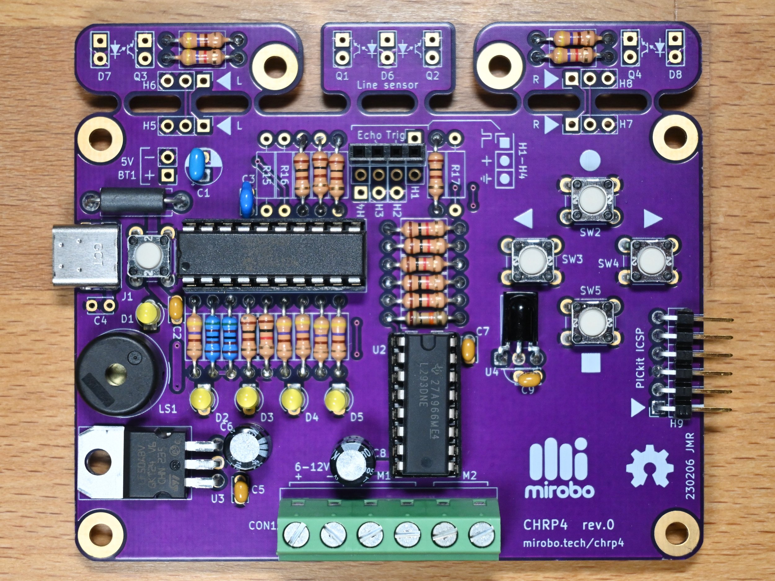
Line-follower Robot
Install the 100Ω resistors R1, and R11-R15.
Install 470Ω resistors R2 and R7-R10.
Install 1.0kΩ resistors R3-6, and R22.
Install 4.7kΩ resistors R16-17.
Install 5.1kΩ resistors R25-R26.
Install 10kΩ resistor R23.
Install USB-C socket J1 by drag soldering.
Install pushbuttons SW1-SW5.
Install 20-pin DIP socket U1, ensuring its notch matches the location of the painted notch on the circuit board silkscreen (closest to the USB-C port). Solder one pin on each side of the chip socket, ensure the socket is properly seated, and then finish soldering the remaining pins.
Install either 16-pin DIP socket U2, or install the motor driver IC U2 in the circuit board directly, ensuring its notch matches the location of the painted notch on the silk screen. Installing the socket for U2 is recommended as it allows U2 to be more easily replaced in case of failure.
Install ferrite F1 – it looks like a resistor, but is dark in colour and has no markings.
Install piezo beeper LS1.
Install 100nF capacitors C2, C5, and C7.
Install 470nF capacitor C3.
Install 10µF capacitors C6 and C8.
Install 1µF capacitor C1.
Install 3mm LEDs D1-D6. The LEDs are polarized and have one long and one short lead. The LED pads on the circuit board are different shapes – one is round and one is square. Install the long lead of each LED into the square pad, and the short lead into the round pad. To ensure the LEDs are installed straight, solder one lead of the LED first, then adjust the LED if necessary before soldering the second lead.
Optionally, install 6-pin header H9. H9 is used for programming UBMP4 using Microchip’s PICkit-4 in-circuit programmer. It is not needed for bootloader programming but can be added to reprogram the PIC16F1459 in-circuit without using the bootloader.
Solder the shorter, silver contact of the header into the circuit board, with the plastic frame laying flat on the board, and leave the longer, gold contacts exposed over the edge of the printed circuit board.Install voltage regulator U3. Bend the leads of U3 downwards 90° with pliers before installing it into the circuit board. Insert a #4-40 screw into the regulator mounting hole from the bottom of the circuit board, through the regulator heat sink tab on the top of the circuit board, and tighten a #4-40 nut on the top of the heat sink tab to hold the regulator in place.
Install screw terminal strip CON1 with its wire terminal openings facing the edge of the CHRP4 circuit board.
Optionally, install IR demodulator U2 and 100nF capacitor C5. The IR demodulator is used to receive IR signals from a TV remote control or a UBMP4 acting as a remote transmitter. Bend the leads at 90° and mount U2 with its flat side against the printed circuit board and with its cylindrical ‘window’ facing up, away from the circuit board.
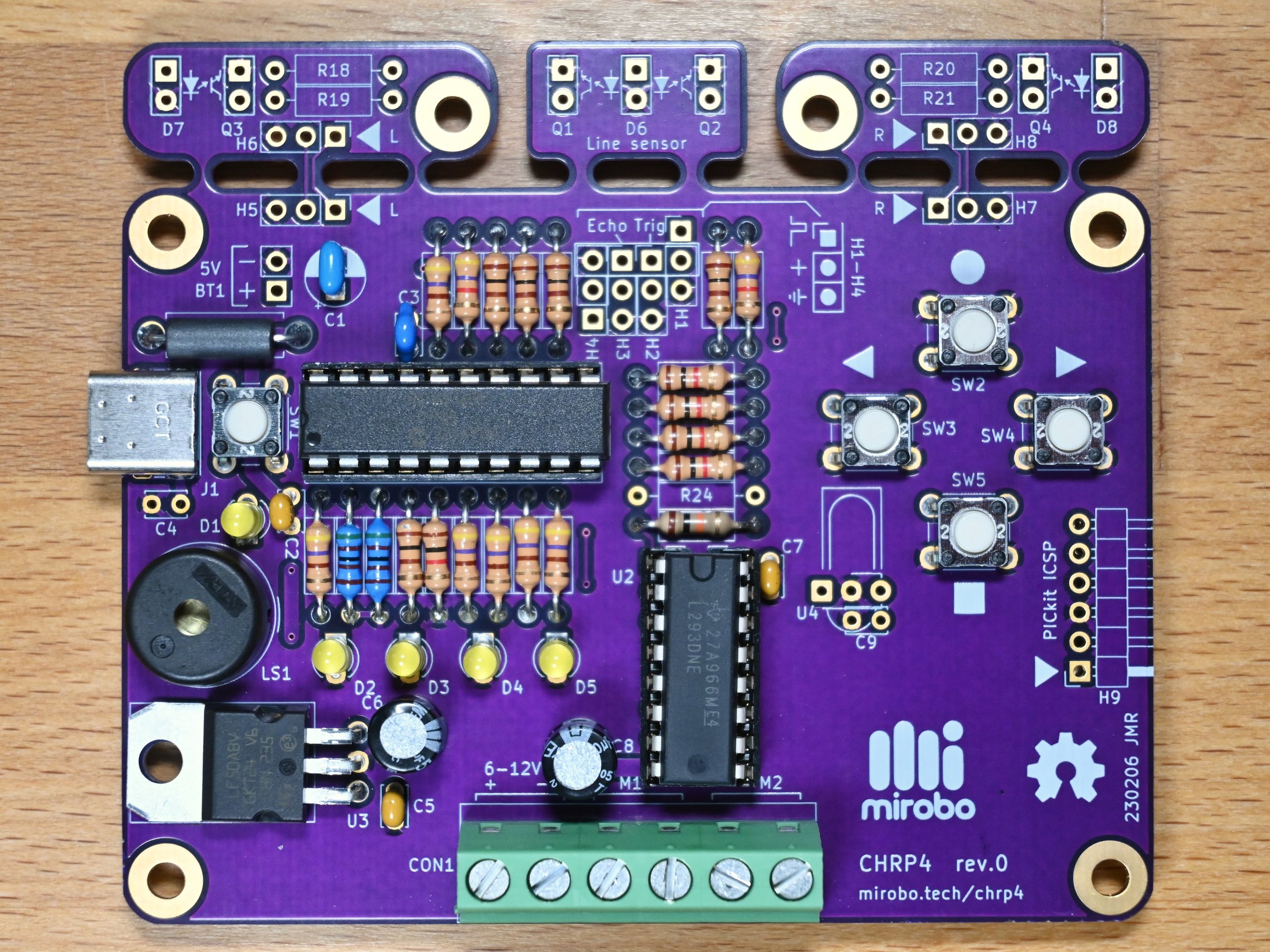
Sumo Robot
Install the 100Ω resistors R1, R11-R14, R18, and R20.
Install 470Ω resistors R2 and R7-R10.
Install 1.0kΩ resistors R3-6, R22, and R24.
Install 4.7kΩ resistors R19 and R21.
Install 5.1kΩ resistors R25-R26.
Install 10kΩ resistor R23.
Install USB-C socket J1 by drag soldering.
Install pushbuttons SW1-SW5.
Install 20-pin DIP socket U1, ensuring its notch matches the location of the painted notch on the circuit board silkscreen (closest to the USB-C port). Solder one pin on each side of the chip socket, ensure the socket is properly seated, and then finish soldering the remaining pins.
Install either 16-pin DIP socket U2, or install the motor driver IC U2 in the circuit board directly, ensuring its notch matches the location of the painted notch on the silk screen. Installing the socket for U2 is recommended as it allows U2 to be more easily replaced in case of failure.
Install ferrite F1 – it looks like a resistor, but is dark in colour and has no markings.
Install piezo beeper LS1.
Install 100nF capacitors C2, C5, and C7.
Install 470nF capacitor C3.
Install 10µF capacitors C6 and C8.
Install 1µF capacitor C1.
Install 3mm LEDs D1-D6. The LEDs are polarized and have one long and one short lead. The LED pads on the circuit board are different shapes – one is round and one is square. Install the long lead of each LED into the square pad, and the short lead into the round pad. To ensure the LEDs are installed straight, solder one lead of the LED first, then adjust the LED if necessary before soldering the second lead.
Optionally, install 6-pin header H9. H9 is used for programming UBMP4 using Microchip’s PICkit-4 in-circuit programmer. It is not needed for bootloader programming but can be added to reprogram the PIC16F1459 in-circuit without using the bootloader.
Solder the shorter, silver contact of the header into the circuit board, with the plastic frame laying flat on the board, and leave the longer, gold contacts exposed over the edge of the printed circuit board.Install voltage regulator U3. Bend the leads of U3 downwards 90° with pliers before installing it into the circuit board. Insert a #4-40 screw into the regulator mounting hole from the bottom of the circuit board, through the regulator heat sink tab on the top of the circuit board, and tighten a #4-40 nut on the top of the heat sink tab to hold the regulator in place.
Install screw terminal strip CON1 with its wire terminal openings facing the edge of the CHRP4 circuit board.
Optionally, install the 4-pin header socket for the ultrasonic SONAR module across all four in-line H1-H4 header pads closest to the edge of the CHRP4 circuit board (alongside the ‘Echo’ and ‘Trig’ labels).
Optionally, install IR demodulator U2 and 100nF capacitor C5. The IR demodulator is used to receive IR signals from a TV remote control or a UBMP4 acting as a remote transmitter. Bend the leads at 90° and mount U2 with its flat side against the printed circuit board and with its cylindrical ‘window’ facing up, away from the circuit board.
Step 4 - CHRP4 final assembly and testing
The top-side components for your CHRP4 configuration have now been installed. Before adding the bottom-side sensor components required for any of the robot builds, your CHRP4 has to be cleaned and tested.
First, inspect the solder connections and ensure there are no short circuits between adjacent component leads. Trim the component leads of the resistors, capacitors and LEDs short enough to minimize the possibility that any adjacent pins can bend over and touch. You may want to trim the switch leads and terminal strip connections to allow the CHRP4 to be mounted as low as possible on your robot platform.
Clean the CHRP4 circuit board using the recommended flux remover for your solder in order to remove any flux residue (unless you used a no-clean flux). Thoroughly dry the circuit board and re-inspect all solder connections.
Set a multimeter to its resistance range and measure the resistance across the BT1 terminals (connect red to + and black to - ). A resistance in the kilo-Ohms range is high enough to ensure there is no short circuit between the power and ground electrical paths.
Align the pre-programmed PIC16F1459-I/P microcontroller so that its notch matches the notch on the U1 chip socket (the notch should be closest to the USB-C connector). Ensure each of the pins is engaged in between the contacts of the chip socket and then firmly press the microcontroller into the chip socket – you may have to carefully bend the pins on each side of the chip inwards, so that they are at 90° to the chip body. If you are building your CHRP4 as a robot, align the notch of the motor driver IC with the notch of the U2 chip socket and install the motor driver into its socket the same way as you did with the microcontroller.
Connect the circuit board to your computer’s USB port using the appropriate USB-C cable. After connection, LED D1 should light to indicate the microcontroller is operating. Press and release pushbutton SW1 to start the bootloader and verify that a device named PIC16F1459 appears in your computer’s file browser.
That’s it! Your CHRP4 is now ready to be programmed. Follow the instructions in one of the programming activities on the CHRP4 page to create your first program. After that, you can build CHRP4 into a line-following, or obstacle-sensing/Sumo robot.
Simple robo assembly
Build your CHRP4 into an inexpensive line-following robot, obstacle-sensing robot, or remote-controlled robot by following the steps to build a Simple Robo platform.
Sumo robot assembly
Are you looking to build a Sumo robot? Watch this space for instructions.