
PIANO2 Introductory Project
When Microchip’s tiny PIC12F1840 microcontroller was released with built-in touch sensor capability, we knew had to do something fun with it. So, we designed a mini pocket piano that uses the microcontroller’s capacitive touch sensors to play eight notes as well as to double as the controls for a metronome – it even includes a selectable beats per measure function!
PIANO2 is our newest introductory circuit for teaching basic component identification and soldering to beginning electronics hobbyists. The limited number of parts also makes PIANO2 ideal as a school or makerspace project since it is inexpensive and can be assembled quickly. The kit includes a microcontroller pre-programmed with the piano and metronome functions, so no programming knowledge is required. Just built it and play!
Tiny piano, grand possibilities
PIANO2 follows our simple projects, big impact philosophy so you can take your learning with PIANO2 further.
PIANO2 is controlled by a tiny computer-on-a-chip known as a microcontroller. The PAINO2 program is provided on our Github page, so you can explore the code and use it as a starting point to develop higher level coding skills if you want to learn more. Try optimizing the touch sensor response, creating unique audio output sounds, or explore other, more advanced coding concepts using the PAINO2 circuit. To do this, you will need a computer running Microchip’s MPLAB X software, a PICkit-4 programmer, and a programming adapter board (coming soon) to enable the microcontroller to be connected to the PICkit-4 programmer.
PIANO2 details
PIANO2 runs on two commonly available AA batteries, which will provide weeks of runtime. As a piano, it plays the eight notes of the A major scale, from a note known as A4 (concert A, at a frequency of 440Hz) to note A5.
PIANO2 also doubles as a metronome, with selectable 40 - 240 beat per minute (BPM) rates as well as 1 - 8 selectable beats per measure. All of the components are included to make a working piano and metronome except for the batteries.
Getting ready to build your PIANO2
Gather all of the required tools and equipment before assembling PIANO2. We recommend:
a soldering iron with a fine tip meant for soldering electronic parts, and a damp soldering sponge to clean the soldering iron tip (If you’re new to soldering, check out this excellent Soldering is Easy comic.)
electronic solder with a no-clean, or water soluble flux
small diagonal cutters or low-profile shear cutters to trim component leads after soldering
a small Phillips screwdriver and needle-nose pliers to attach the battery pack
Step 1 - Check your components
First, confirm that you have all of the required and optional components in your kit. You can use the PIANO2 schematic diagram to identify each component and examine how they they are connected to make the circuit.
PIANO2 circuit components
1 - PIANO2 printed circuit board
1 - 100Ω, 1/4W resistors (colour code: brown, black, brown, gold)
4 - 1.0kΩ, 1/4W resistors (colour code: brown, black, red, gold)
1 - 6mm pushbutton
1 - 8-pin DIP (dual-inline package) IC (Integrated Circuit) socket
1 - 100nF ceramic monolithic capacitor (numeric code: 104)
1 - 17mm piezo beeper (non-polarized)
1 - dual AA battery holder with PCB pins
1 - PIC12F1840 microcontroller
1 - M2.5 nylon screw
1 - M2.5 nylon nut
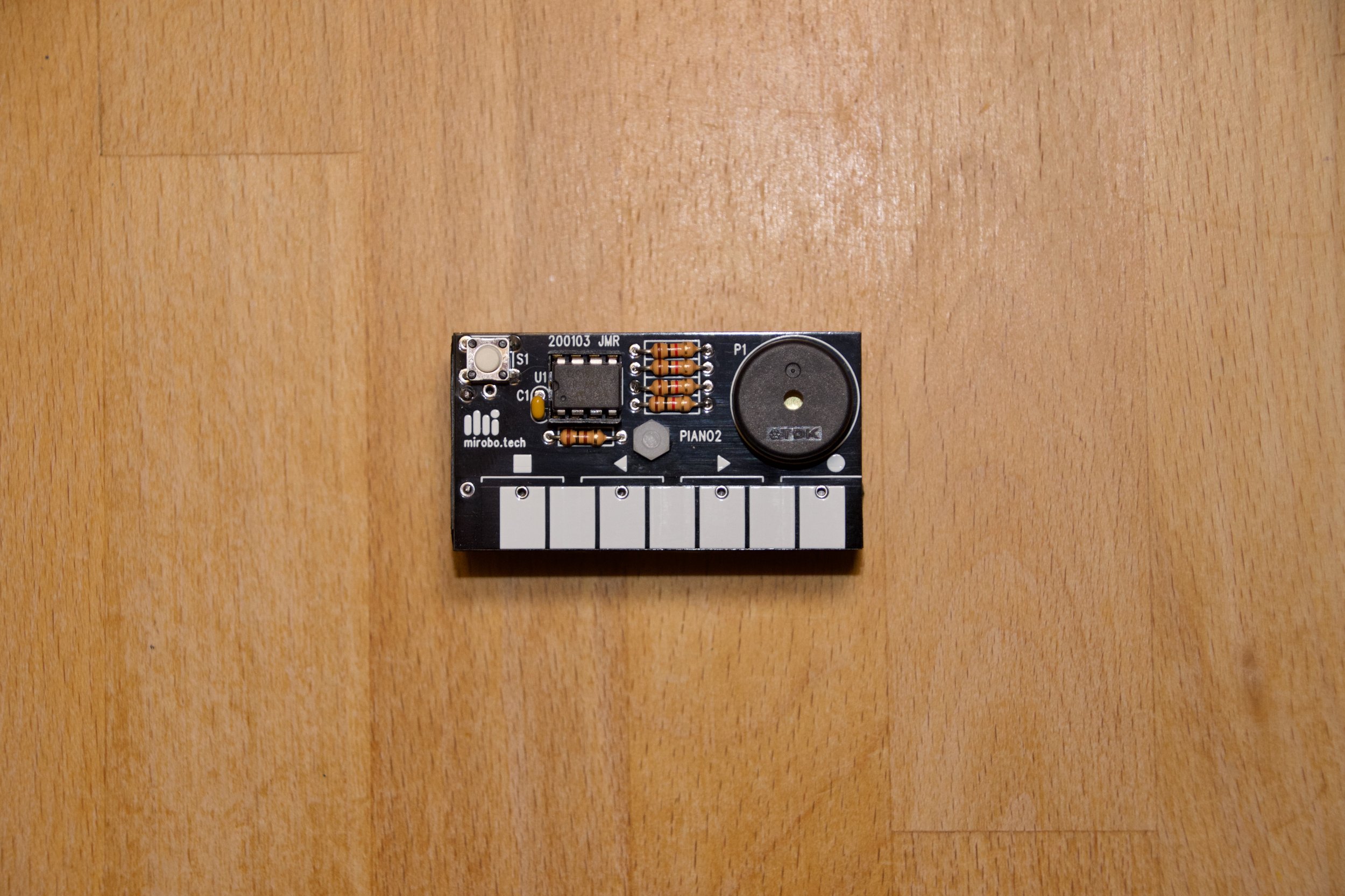
PIANO2 operating instructions
PIANO2 has three modes of operation: piano mode, metronome mode, and off mode. Select the operating mode by pressing, briefly holding, and then releasing pushbutton S1.
Piano mode
When the batteries are first installed, PIANO2 wakes up in piano mode. Touching each of the white ‘keys’ will make the first seven notes of an A major musical scale. Touching both the first and last keys at the same time will make the eighth and highest note of the scale. From piano mode, press and release pushbutton button S1 to switch to metronome mode.
Metronome mode
The shape symbols above the keys indicate the metronome function of each key.
Square - starts and stops the metronome. It remembers the last used speed and beats per measure setting until the batteries are removed.
Arrows - decrease or increase the metronome beats per minute rate in steps of 5, from 40 to 240 BPM.
Circle - increases the beats per measure from 1 to 8. At 1 beat per measure the metronome beats at a single pitch. Increasing the beats per measure makes a higher pitch first beat followed by lower pitch beats to complete the measure.
From Metronome mode, press and release pushbutton S1 to switch to off mode.
Off mode
Off mode isn’t really off, but it is a low-power nap mode for the microcontroller. It’s best to remove the batteries if PIANO2 will not be used for an extended period of time.
Step 2 - Solder the circuit board components
Components are installed in order from smallest to tallest to make installation easier. Component orientation does not matter for the resistors, pushbutton, capacitor, or piezo beeper. Important installation and testing details will be described for the chip socket, microcontroller, and battery holder in the steps below:
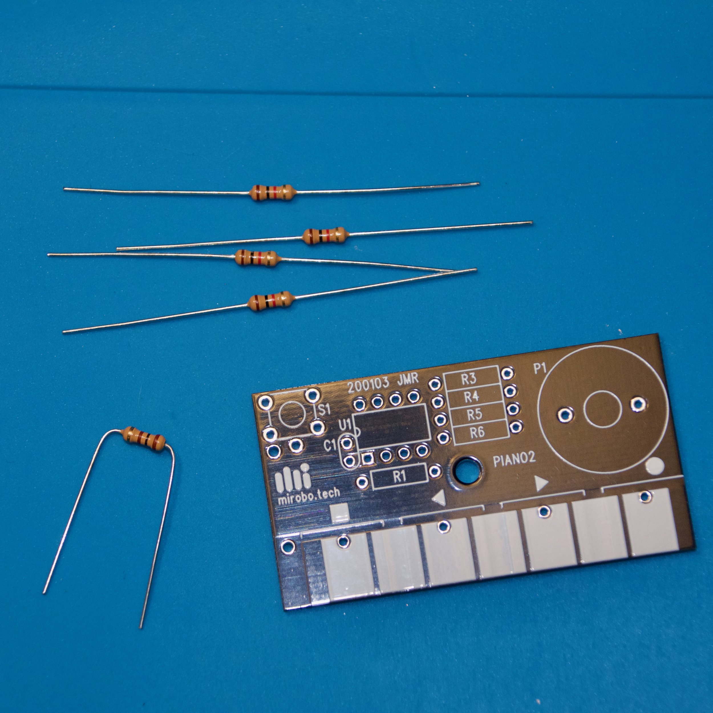
2.1 Start with the resistors. R1 is the only 100Ω resistor and has brown, black, brown, and gold stripes. Gently bend its wire leads into a u or n shape.

2.2 Insert the leads into the metal pads at either end of the rectangular symbol for R1. Flip the circuit board over and gently spread the leads a bit.

2.3 Solder each lead of R1 to its pads using a minimum of solder. Cut the leads right above the solder connection, and try to cut them as low as you can above the solder connection.

2.4 Bend the leads of the four 1kΩ resistors and solder them into the remaining resistor spots as you did with R1. Align the little notch on the IC socket with the painted notch (near C1) on the circuit board. Carefully insert the IC socket making sure all pins go into their pads and through to the other side.

2.5 Solder just one pin on each side of the IC socket and flip the board over to verify that the socket is straight and level. If it isn’t, you can re-heat one of the pins you soldered and gently push the socket into place to make it straight. Ensure all of the remaining IC socket pins go through to the bottom of the board and finish soldering all of them. Then insert capacitor C1 and switch S1 into the board and solder their pins.
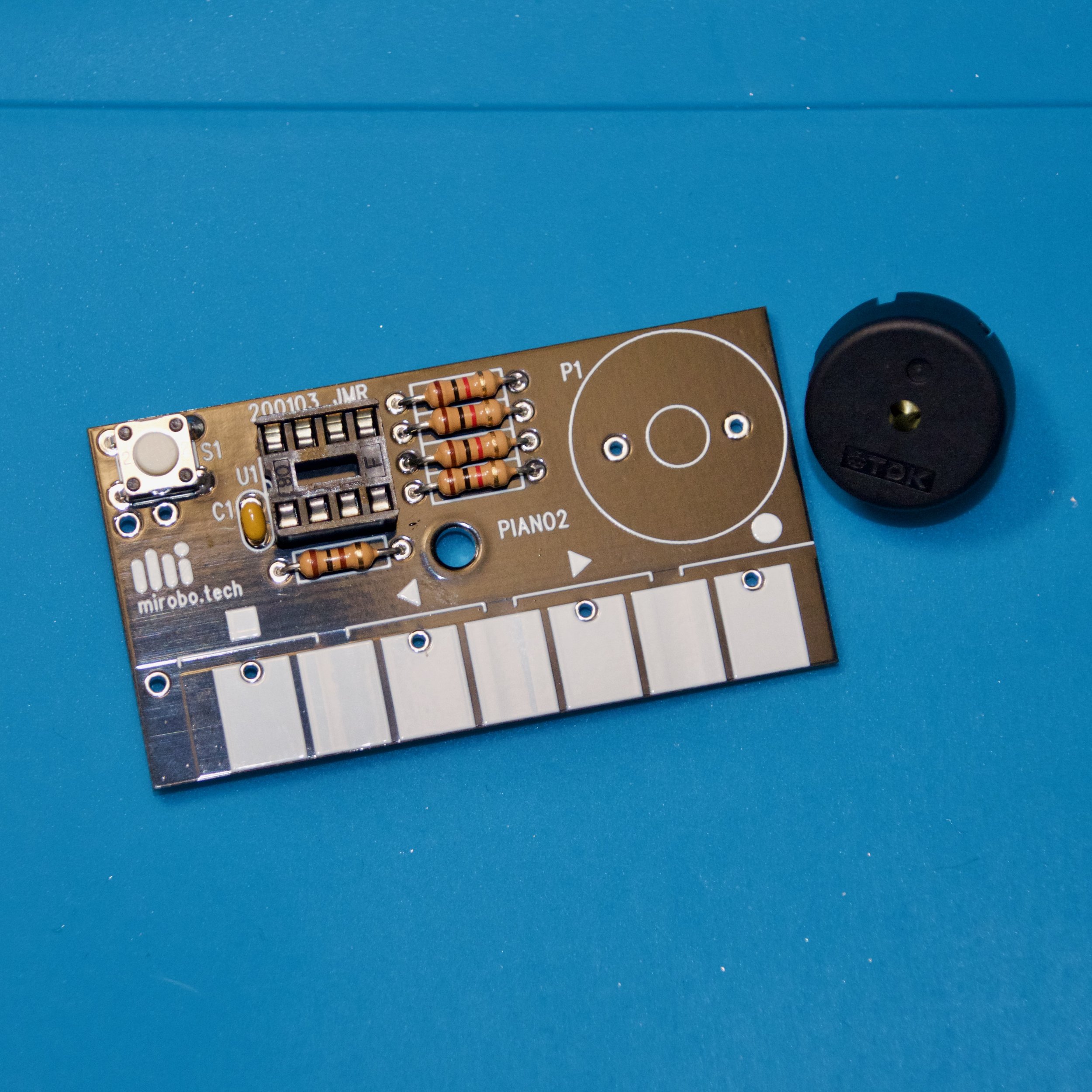
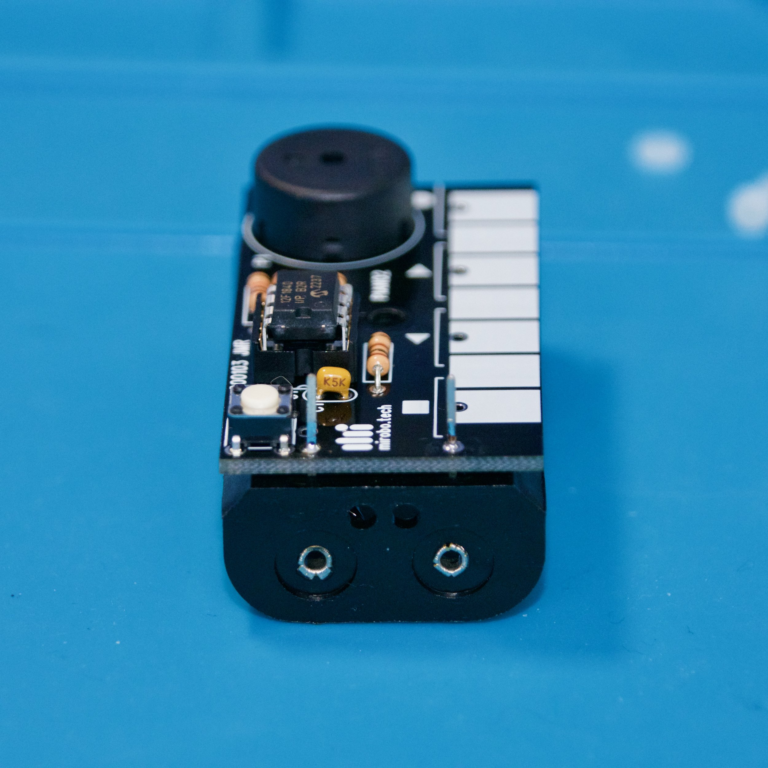
2.6 Trim the leads of all of the components, including the switch and the IC socket – this will help us to mount the circuit straight and level on the battery pack later. Insert the piezo beeper into the circuit board, solder it into place, and trim its leads. Carefully inspect all of your solder connections and fix any that don’t have enough solder, have too much solder, or are shorted to an adjacent pad.
If you soldered your circuit board components using solder with a no-clean flux, you are ready to proceed to the next step.
Other types of solder require the solder flux residue to be cleaned from the circuit board. If your solder uses a water-soluble flux, cover the hole in the piezo beeper with your finger to prevent water ingress and run warm water over the solder side of the circuit board to remove the flux. Shake, or tap out any excess water, dry the circuit board completely before proceeding to the next steps.
If your solder uses any other type of flux, use the flux remover recommended by the manufacturer of the solder and precisely follow the directions for its use to remove all of the flux before continuing on to the next steps.
Step 3 - Test and finish the circuit
These next steps are very important! The circuit board needs to be tested before the battery pack is permanently attached. If you attach the battery pack first and then find a problem with your circuit, you risk damaging both your circuit board and the battery pack if you try to remove it.
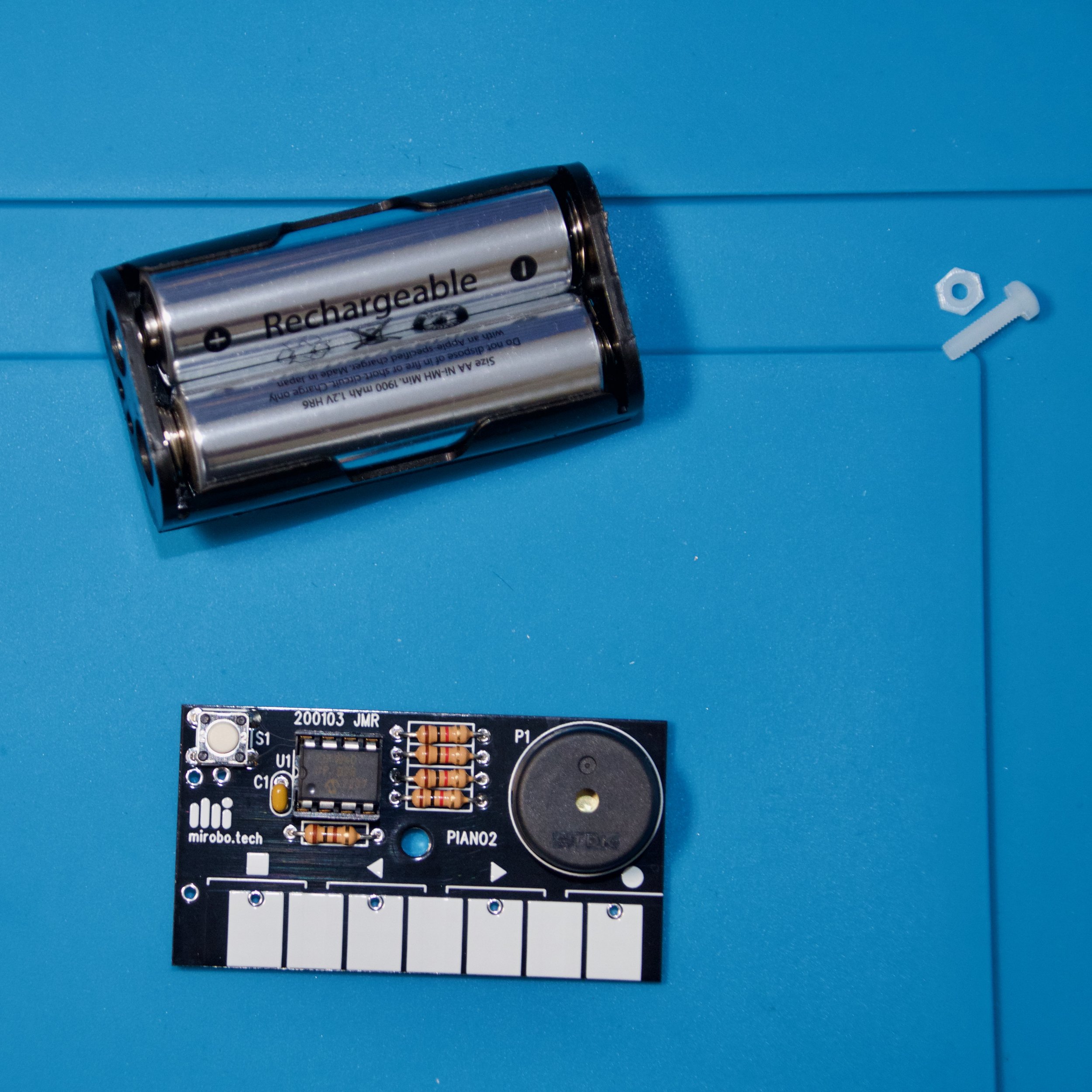
3.1 After your circuit board is clean and dry, align the notch or dot on the PIC12F1840 microcontroller with the notch on the IC socket and press its pins firmly into place in-between the metal contacts of the receptacles in the IC socket. Insert two AA batteries into the battery holder for testing in the next step.

3.2 Inset the battery holder (with the batteries in it) into the two remaining pads along the left edge of the circuit board. Press the circuit board against the battery holder pins to ensure good contact between the pads and the pins, and touch the keys to ensure the piano plays a note for each key. Press and release pushbutton S1 to verify that the metronome beats. If some of the keys or the pushbutton do not work, or there is no sound at all, remove the battery pack and carefully re-check all of your solder connections. After fixing any connections, verify that your batteries are good, and re-test the circuit.
3.3 If both the piano and metronome functions worked in your testing, solder the battery holder pins on the top side of the circuit board while keeping the circuit board as close to and as level with the battery pack as possible. This will be easier if all of the component leads have been trimmed to the same length. Alternatively, you could cut a rectangle of cardboard, felt, or thin foam and sandwich it in between the circuit board and the battery holder to help align the two pieces and keep them level when soldering.
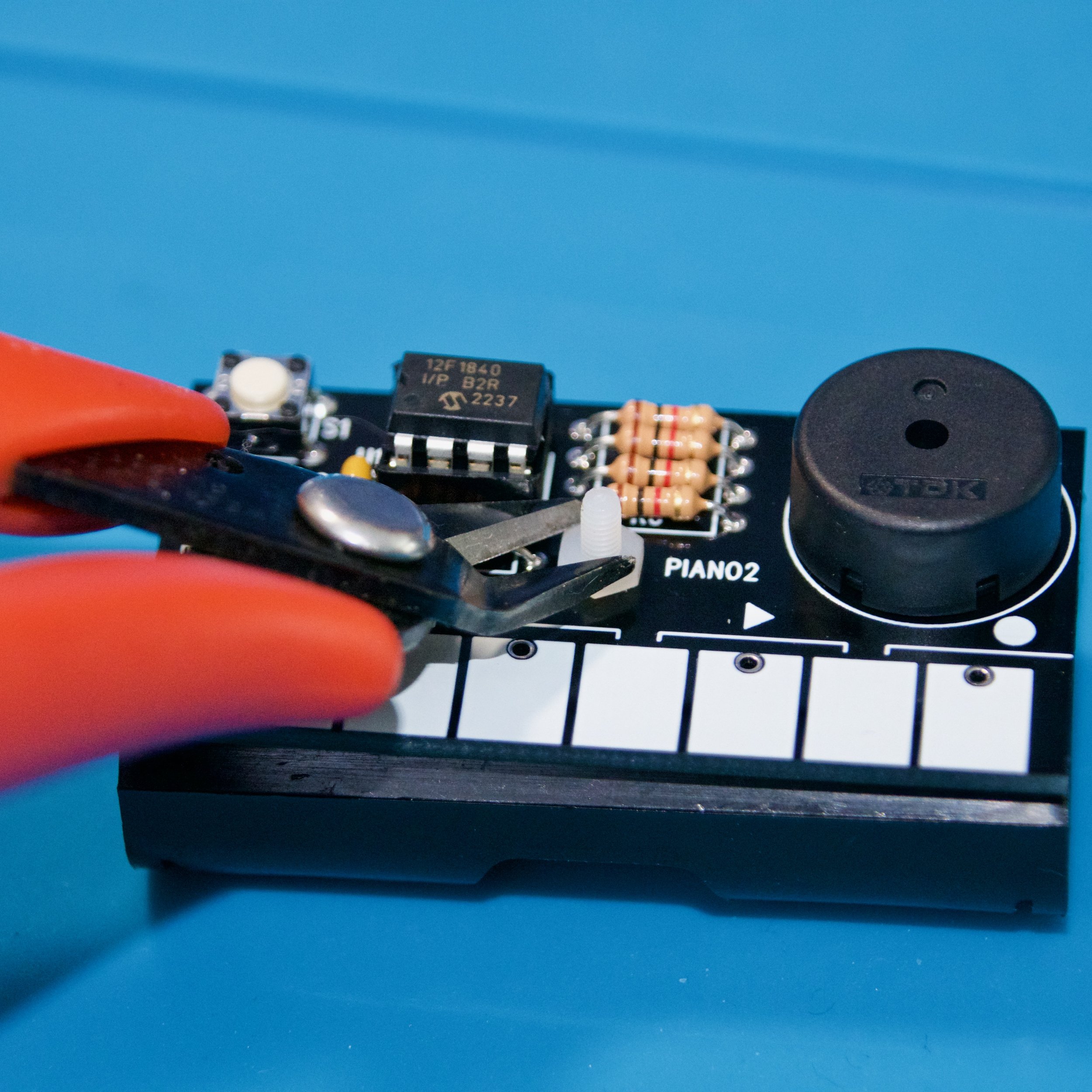
3.4 Insert the nylon screw through the hole in the battery holder and up through the hole in the circuit board. Attach the nut on the top of the circuit board – it’s easier if you hold the nut with pliers as you turn the screw. Turn the screw just until it starts to become tight. Do not over tighten it! You can trim the excess length of the screw using shear cutters or a hobby knife.
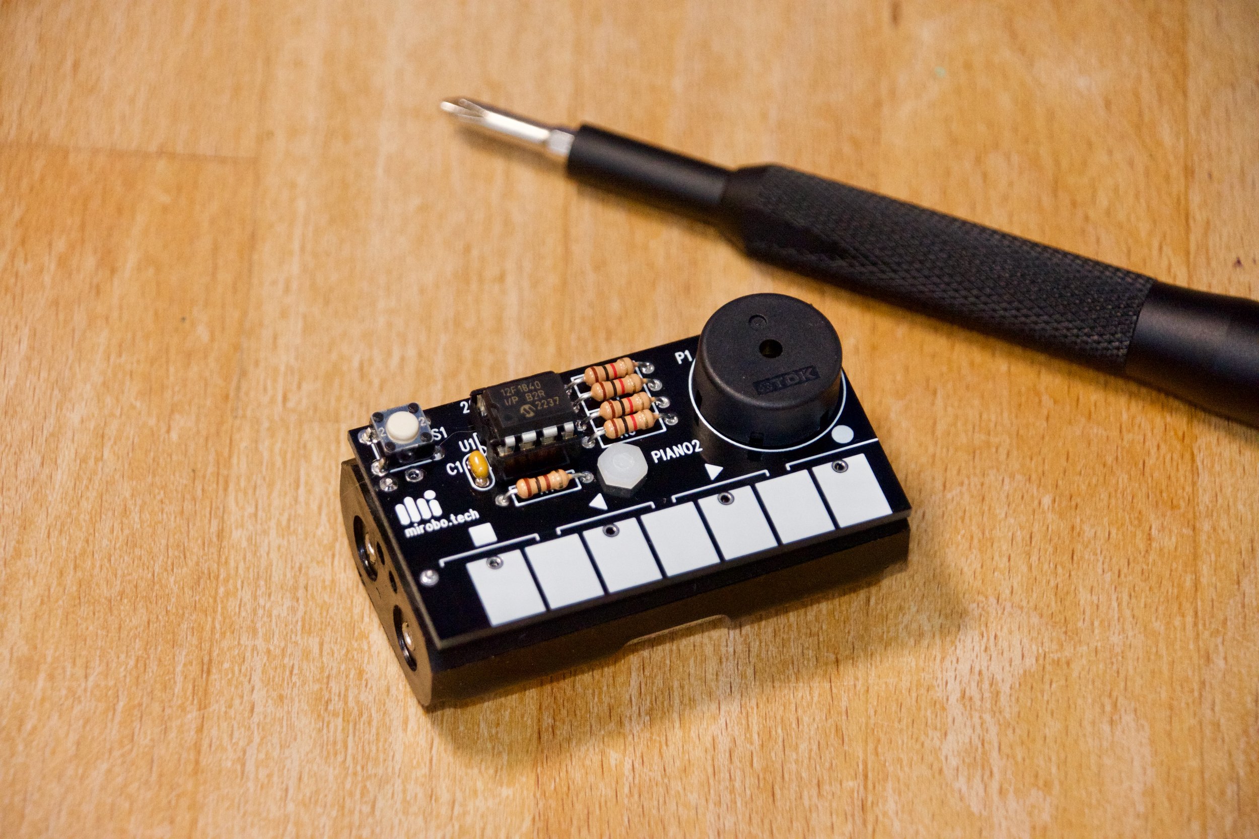
That’s it! Your PIANO2 is done and ready to play. Read over the operating instructions at the top of this page, and remember to remove the batteries if it will not be used for an extended period of time.