
Simple robo
Build a super-simple and inexpensive robot platform.
It’s ideal for making line-following robots in schools!
There are many solutions for making robots using expensive gear motors, servo motors, and stepper motors. This practical robot platform has been designed for what matters most in a classroom: simplicity, low cost, and easy assembly by students.
What’s so special about this design?
This simple robo base was created to enable high school computer technology students to each build their own, take-home, line-following robot project. Here are some of the design decisions that helped to make it a success:
the simple robo is powered by two inexpensive DC motors (not not gear motors) which are commonly available from local surplus electronics stores. Using DC motors allows a robot to be controlled using simple microcontroller I/O port commands instead of using more complicated servo pulses, or stepper motor wave trains. Try to find DC motors with flattened sides to make mounting easier than using round motors.
the steel axle floats in a slot cut into the platform material making it self-adjusting for slight variations in motor size, platform thickness, wheel sizes, and even wheel holes that have been drilled slightly off-centre!
the DC motors drive o-ring tires through friction, from the weight of the robot resting on the tires. This provides speed reduction similar to a gearbox with the added ability to slip freely when the robot hits an obstacle so there can never be any broken gears.
the third ‘wheel’ is an inexpensive chair glide – screw or glue it into place on the bottom of the platform.
the robot chassis/platform is made of inexpensive MDF (medium-density fibreboard) which can be easily cut and drilled by students to mount the functional robot parts (motors, batteries, circuits, sensors, etc.), as well as being sandable, paintable, and ideal for mounting optional decorations, too! Other materials, instead of MDF, can be substituted if they are readily available.
the wheels are cut from a length of wooden dowel – think closet rod – or can be made using a 3D printer. A school’s wood shop can be enlisted to cut the materials for the wooden wheels and bases, or an inexpensive sliding mitre saw will do the trick.
the axle is a length of hardened steel wire, also known as ‘music wire’, which is available at many hardware stores and hobby shops. We’ve also seen welding rod and thicker coat hanger wire being used successfully.
the nylon nuts are the most important pieces, and are the key to making this project work. Think of the interior screw thread of the nylon nuts as being similar to the fingerprint ridges on your fingers – the points of the screw thread deform slightly and provide a tight grip on the axle to mount the wheels. Try to buy these in bulk from a specialty fastener supplier to get them at the lowest cost.
Materials and tools
You will need a variety of materials to make the robot base:
1 - 5/8” thick MDF (adjust based on your motor size) or other material for the robot base
2 - DC motors (we usually use 6V motors, but low current 3-12V motors will work, depending on your application) with plain, round (gear-free) output shafts
1 - 3/32” dia. steel (music wire) axle, approximately 1” longer than the width of your robot base. We use this K&S music wire.
4 - #4-40 nylon nuts
2 - 1-1/8” diameter dowel, to make wheels. Cut into approximately 1/4” width discs.
2 - 0.984” I.D., 0.125” thickness (commonly specified by suffix -214) o-ring tires, or a size that fits snugly onto your wheels
2 - 1” pieces of double-sided foam tape
2 - 8” - 10” long plastic cable ties (depending on motor diameter and platform thickness)
1 - plastic chair glide (screw-on or self-adhesive)
7 - #4 x 1/2” wood screws to mount the circuit board, battery pack and chair glide to the MDF base
You will have more success if you have access to a few specialized tools:
10” table saw or sliding mitre/radial arm saw to cut the MDF base to size, as well as to cut the axle slot into the MDF base, and for cutting the dowel to make the wheels
Dremel tool with a fibreglass cut-off disc to cut the music wire axle to length
a metal file to file the ends of the axles
a drill press and assorted drill bits to drill the mounting holes for the motors and other components, as well as to drill the axle hole in the wheels
pliers to tighten the cable ties
a hammer makes it easier to fasten the nylon nuts onto the axle.
Simple robo materials
The simple robo platform design is ideal for introductory robot projects in schools due to its low cost.
Some suggested materials and material sources are listed, below:
Robot chassis/base - MDF (medium density fibreboard) is inexpensive, dimensionally stable, heavy, and easy to cut, drill, sand and paint.
Wheels and tires - perfectly round by design, cut sections of a closet rod dowel and add a plumbing o-ring for grip.
Chair glide - a plastic chair glide is a low-friction alternative to a third wheel or omni-wheel used in more expensive robot designs.
Buy all of the above parts for the bases from your local hardware or building store. Or, get creative – you might find a local manufacturer that is more than happy to give you their scrap MDF or plastic rod!
DC motors - low voltage (6V - 12V) DC motors are often available from electronics surplus stores. Look for motors with a low current draw and a long output shaft without an output gear.
Axles - use 3/32” steel wire from a local metal supply shop or hobby shop.
Nylon axle nuts - these are the most difficult to source and have to be properly sized to fit the axles. Most fastener suppliers can order them for you if they don’t have them in stock.

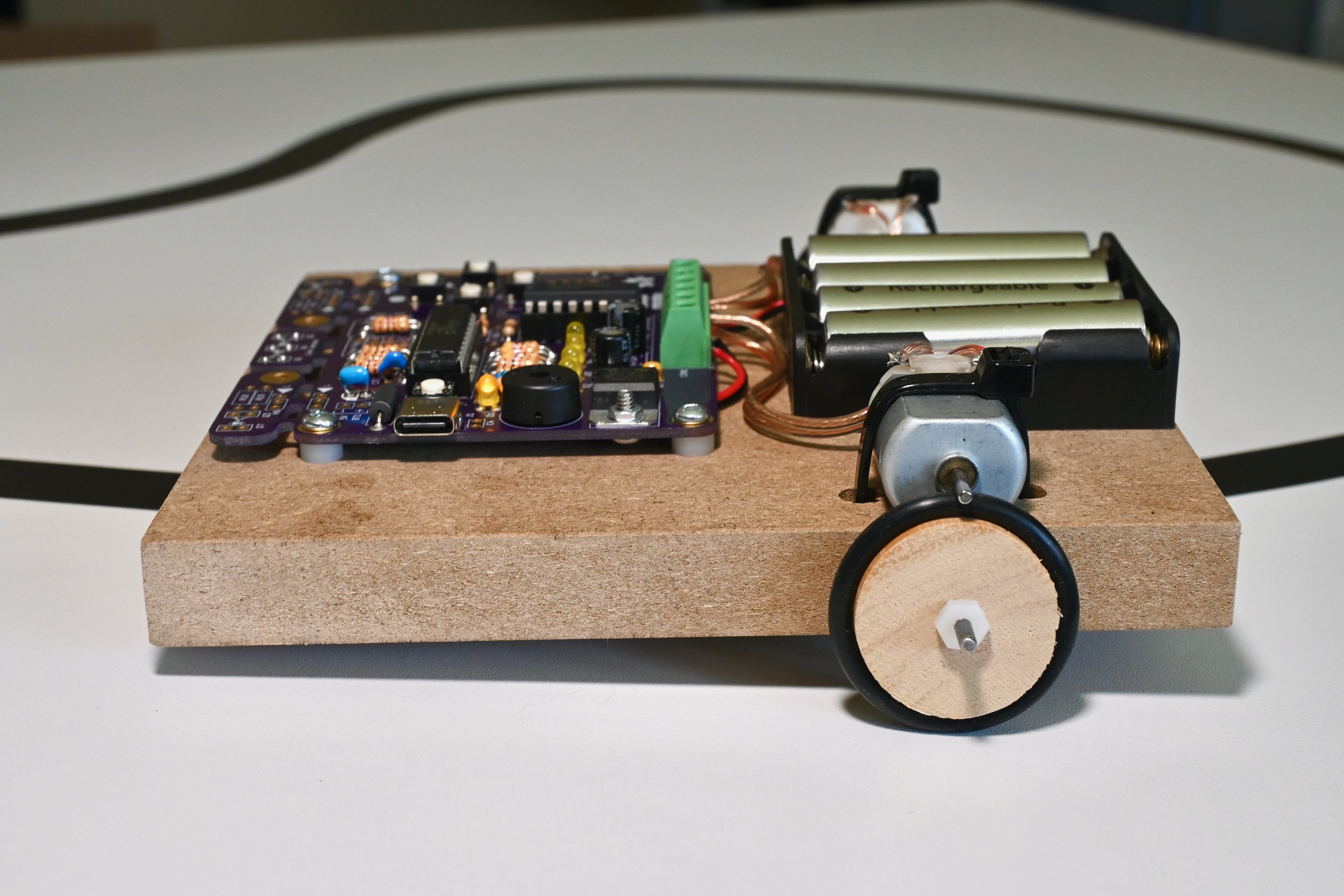
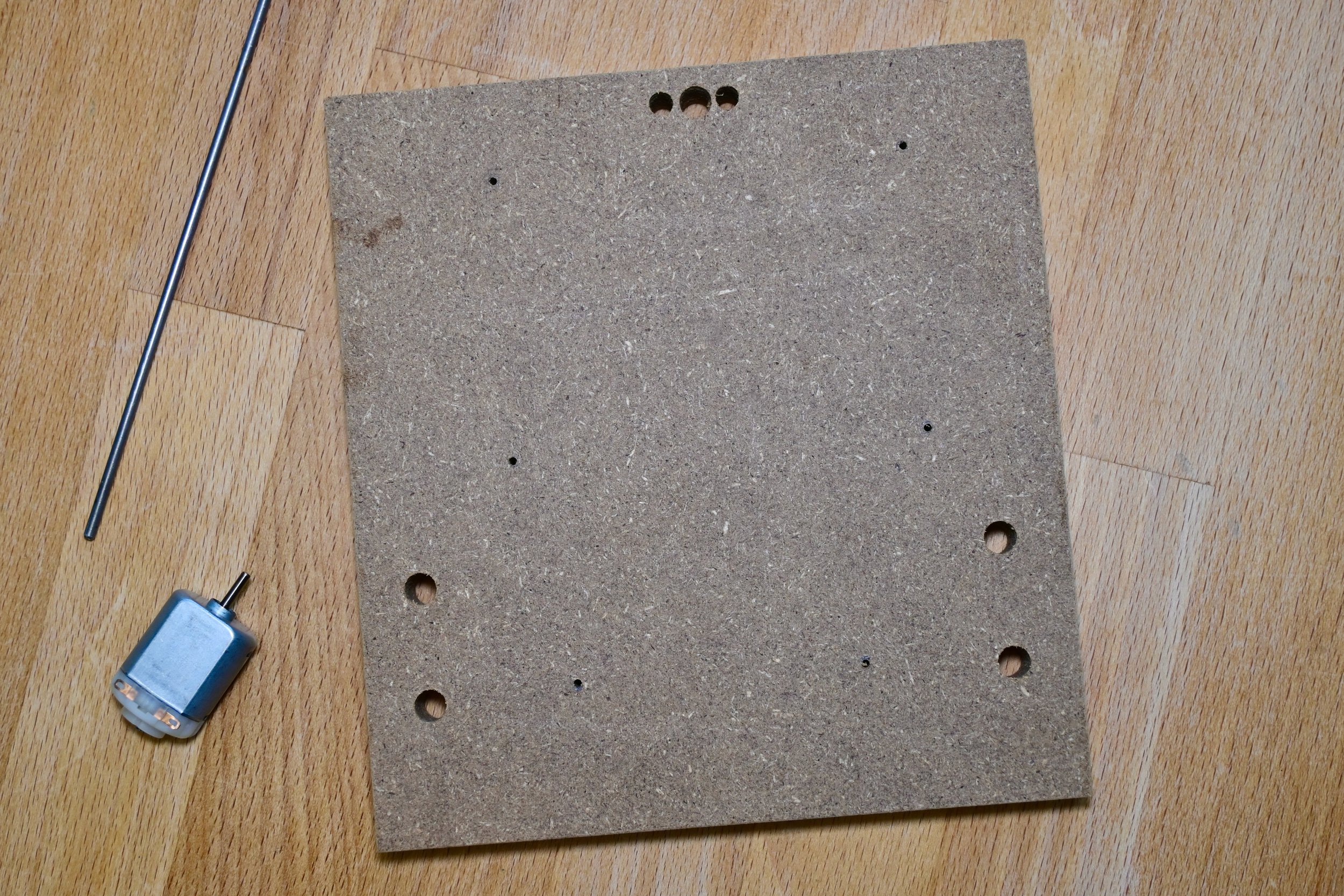
Here are all the materials you will need to build a simple robo. We’ve designed the size of the platform to hold CHRP4 and 4-AA batteries.
Build it
Step 1 - Plan your robot design and cut the platform to size. Then, cut the axle slot.

This example design is based on building a line-following robot using:
2-DC motors
a 4-AA battery holder
the CHRP4 circuit built in the line-following robot configuration
The platform size for this design is 5.875” long and 5.5” wide (these sizes were chosen to minimize the amount of scrap wood and axle rod for this design, but feel free to use whatever size fits your parts best).
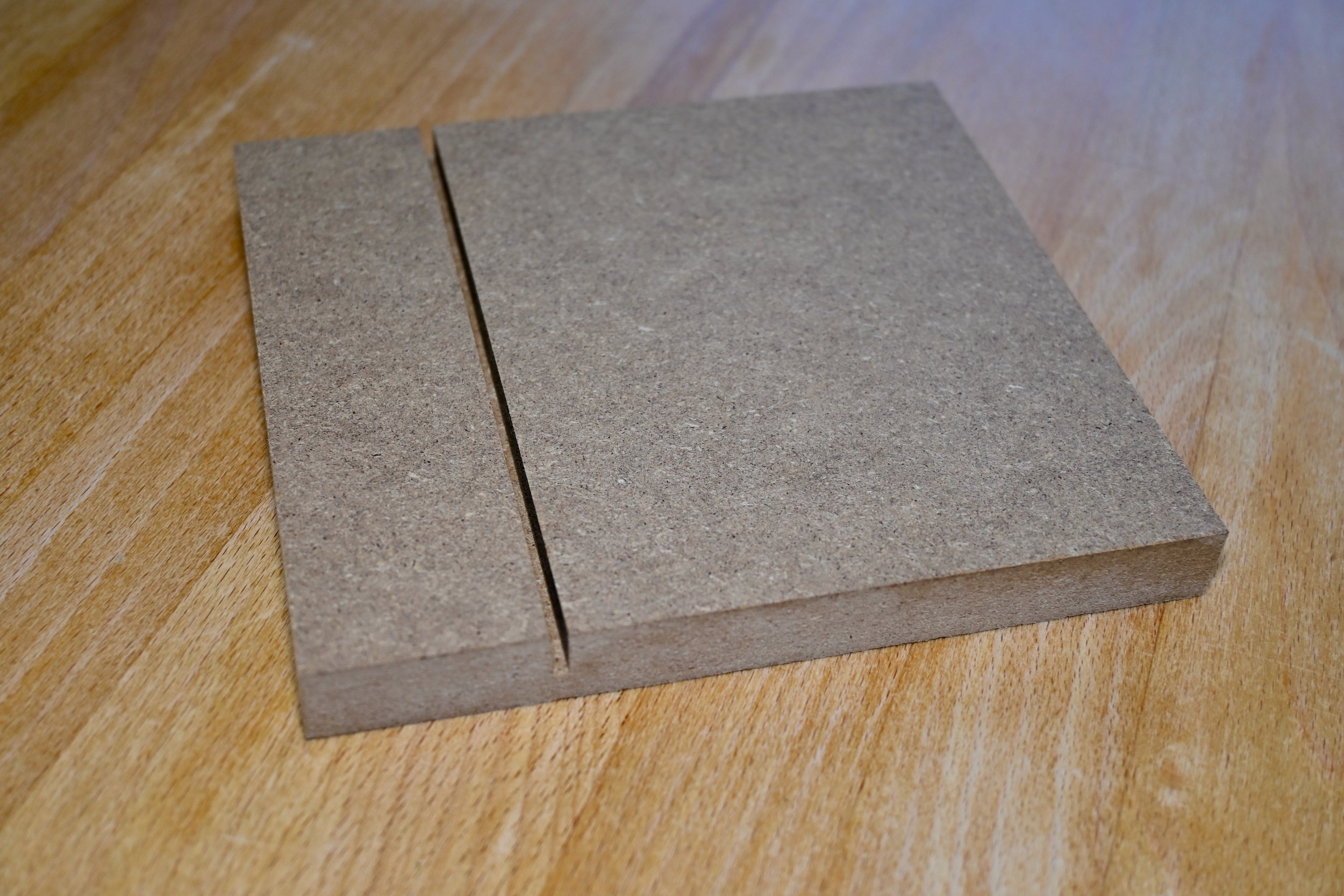
Cut the platform to size using a table saw or similar. Next, cut an axle slot approximately half-way through the platform. The axle slot will be on the bottom, and a typical table saw blade kerf (the width of the blade) will fit the 3/32” axle rod. This axle slot is positioned approximately 1.5” from the back edge of the robot.
The position if the axle slot is not critical, but make sure you avoid the mounting hole areas of the motors, battery pack and, circuit board. Positioning the axle slot further back is ideal for line-following robots, while a more centred design may be better for other robots.
Step 2 - Mark all component mounting hole locations
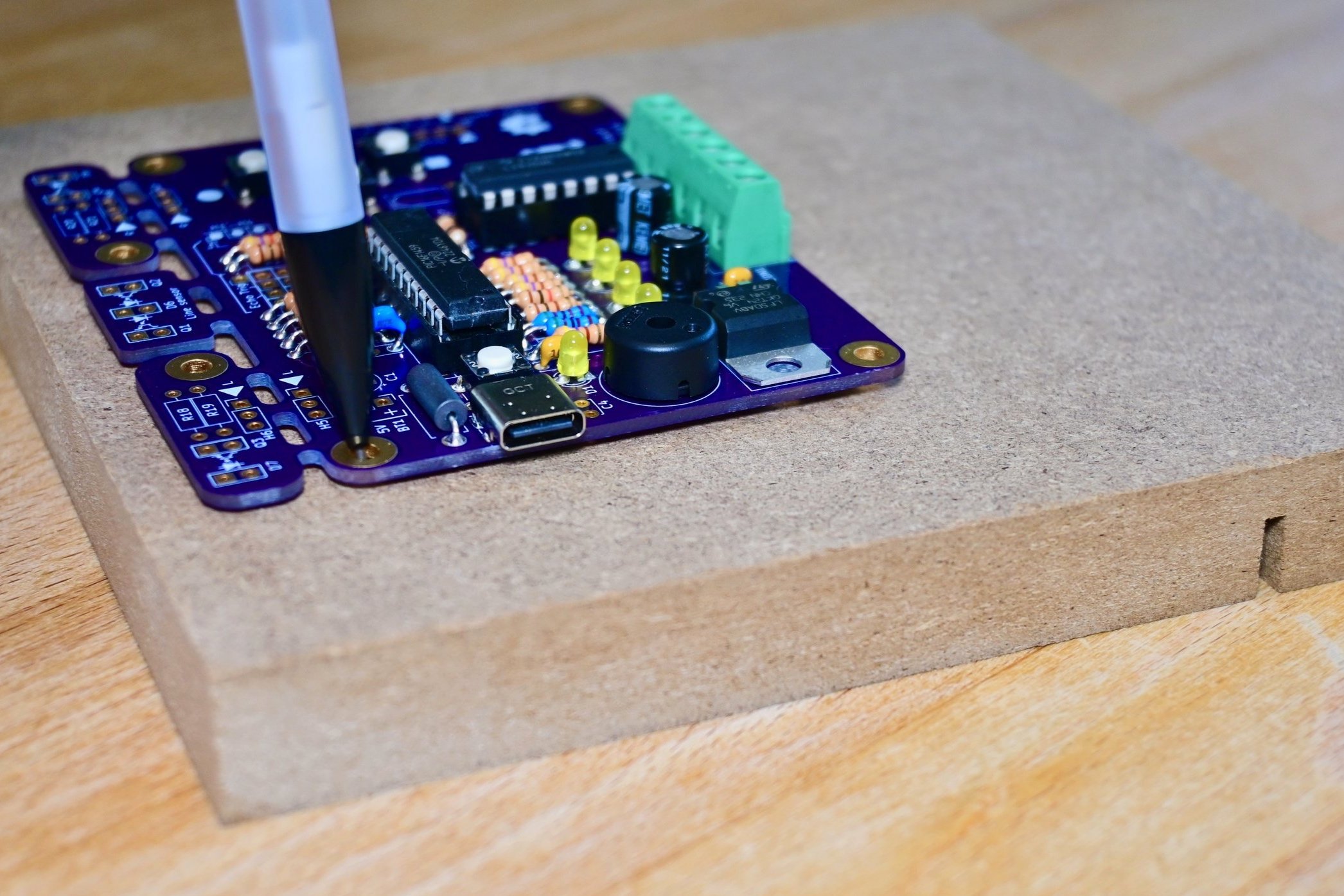

Mark the mounting hole locations for the circuit board.
Bonus tip for CHRP4!
If your circuit board needs to mount the floor sensors on-board, as CHRP4 does, you can use a 0.5mm mechanical pencil to mark the position of these parts. With the CHRP4 positioned in its mounting location on the simple robo platform, insert the pencil lead through each LED and phototransistor pad on the circuit board while twirling the pencil to mark mark the location of each of these on the platform.
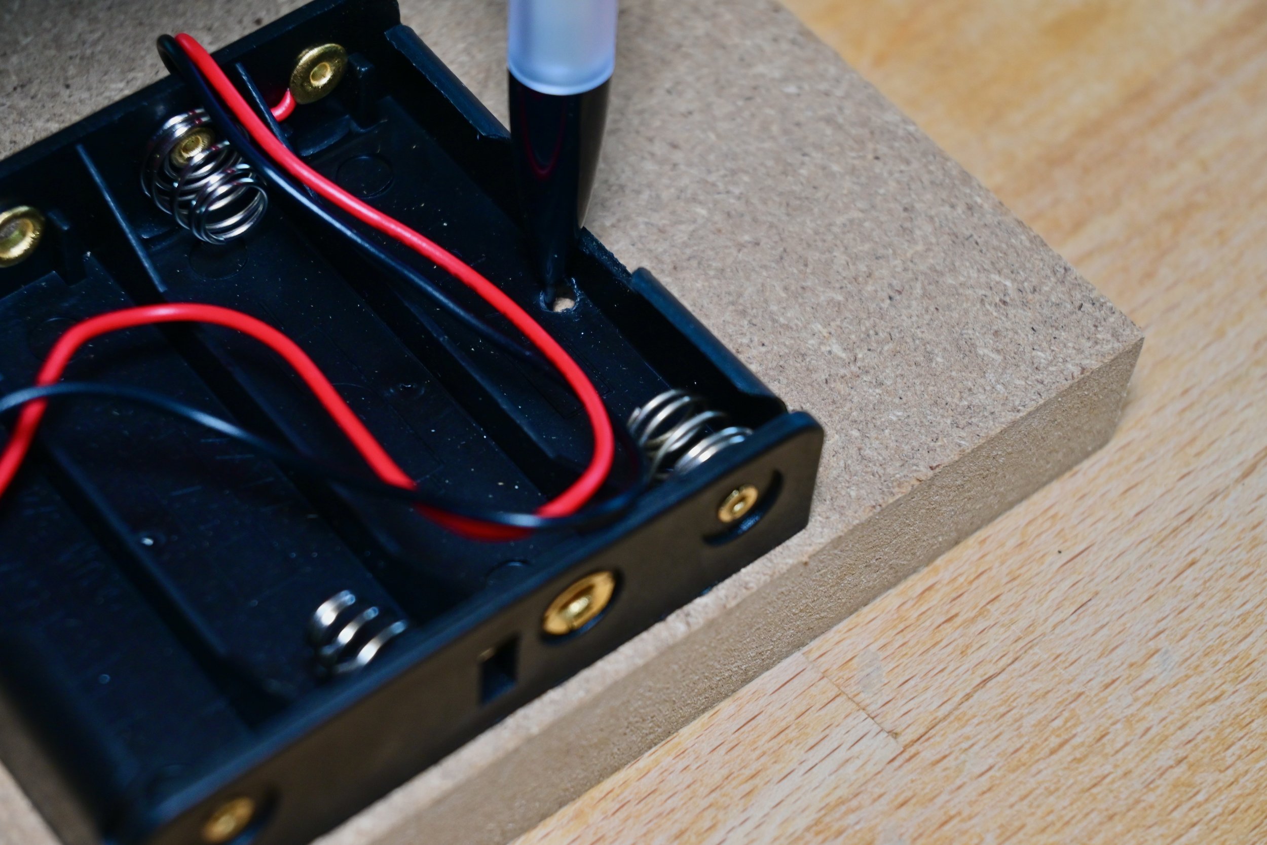

Mark the locations of the battery holder and motor mounting holes.
Align the motor with the edge of the platform and directly over the axle slot. Make a mark along each edge of the motor, directly below the widest part of the motor, and approximately in the middle of the motor’s length.
Step 3 - Drill all of the mounting holes


If your mounting holes included the location of the optical sensor leads, connect the two dots you made for each LED or phototransistor lead and mark the middle of the line between the two dots to mark the component’s actual location.
After marking all of the mounting holes, drill the holes using the recommended drill sizes, below:
use a 1/16" drill bit for the circuit board, battery holder, and chair glide mounting holes (any parts that will be mounted using a #4 screw)
use a 1/4" drill bit for the motor mounting holes, and for any 5mm floor sensor LEDs (the centre hole for D6 on the CHPR4 board)
use a 3/16" drill bit for the 3mm phototransistor silos (Q1 and Q2 on the CHRP4 board) – be sure to leave about 1mm of wall thickness between the LED and phototransistor holes
If you would like to paint or decorate your platform, a great time to do so is after drilling all of the holes.
Step 4 - Mount the motors and chair glide
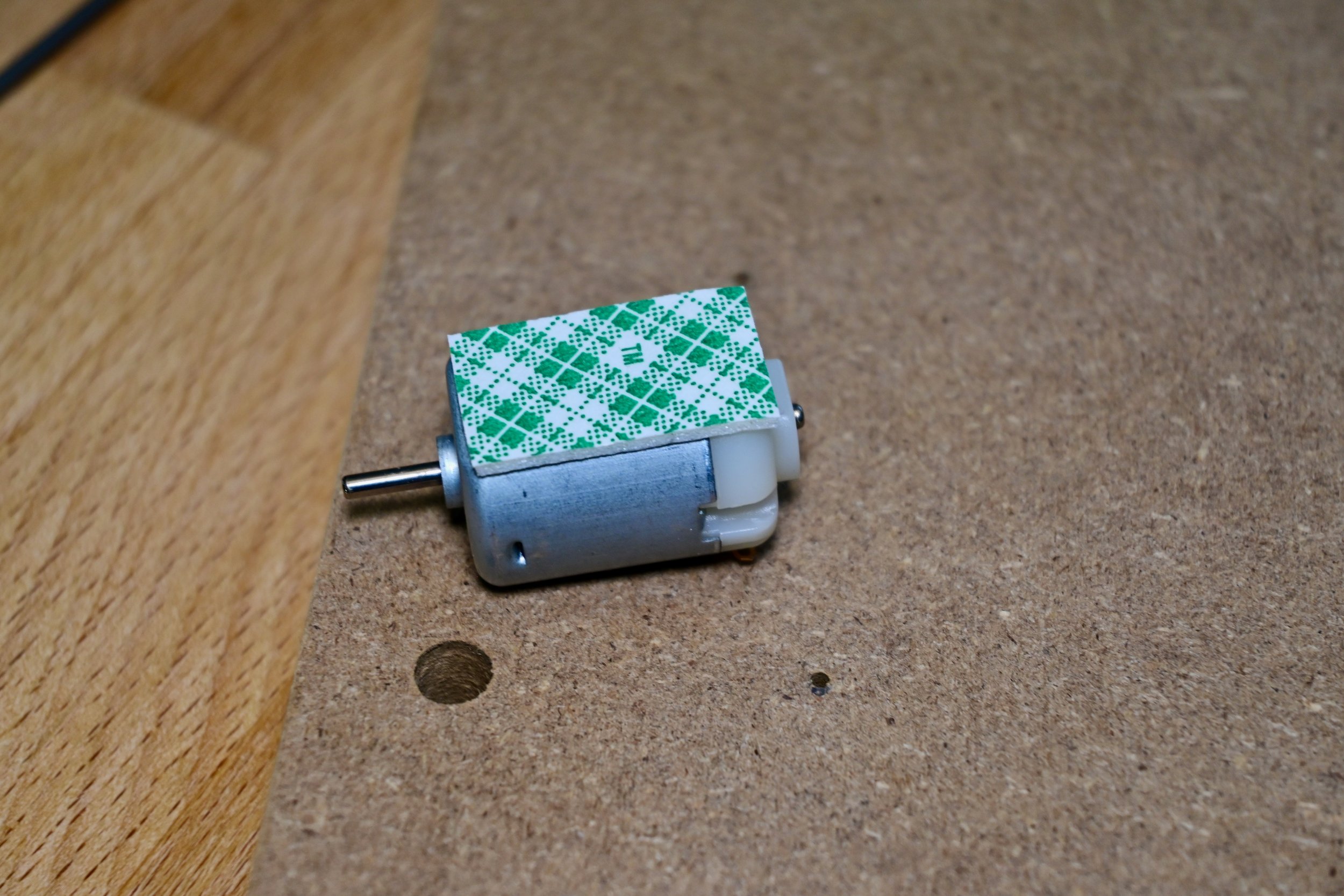
Cut a piece of double-sided foam tape to fit each motor. The tape will prevent the motors from sliding on the MDF platform.

Align the edge of each motor over the edge of the platform, with the motor shaft directly over the axle slot and stick the motor into place. Insert a cable tie from the motor side, through the 1/4” motor mounting holes in the platform, and fasten it on the top of the motor.

Pull the cable tie really tight so that it lays flat across the axle slot and cut it above the fastener.
Screw the chair glide into the 1/16” mounting hole (or stick it on if using a self-adhesive chair glide).
Step 5 - Prepare the axle and mount the wheels

The rough-cut axle end has to be smoothed and rounded so that it can be pushed into the #4-40 nylon nuts without damaging the interior thread.

Hold the axle at a 45° angle and use a file to round off the edge while slowly twirling the axle between your thumb and fingers.

The axle should have a smooth, chamfered edge when you are finished.

Drill the centre of each wheel using a 7/64” drill bit and pull mount the o-ring onto the outside of the wheel.
Push one #4-40 nylon nut onto the axle (this will become the inner nut). If it’s too difficult to push it on by hand, set the nut over the wheel hole, align the axle with it, and give it a gentle tap with a hammer.

Slide the wheel onto the axle up to the position of the inner nut, and slide a second outer nut onto the axle to secure the wheel.
Push the axle through the axle slot in the robot platform and add an inner nut, the second wheel, and an outer nut on the other side of the robot.

Adjust the position of the wheel nuts making sure that:
the axle can freely float up and down in the axle slot – slide the inner nuts so there is a 1mm gap between the platform and one of the nuts
each wheel can spin freely – slide the outer nut so there is a small gap on each side of the wheel
A hobby knife or a small, flat-bladed screwdriver can be inserted between the platform and the inner nuts to help adjust them.
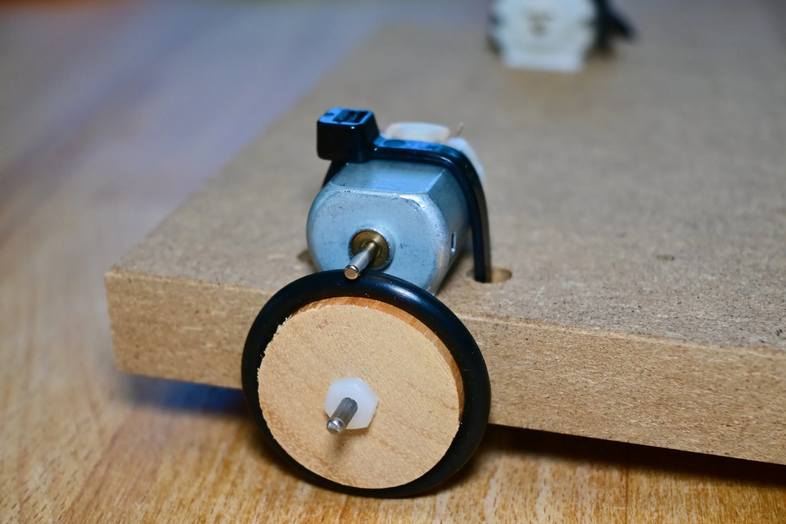
You did it! Here’s what the finished motor, axle, and wheel assembly looks like. The weight of the robot and the axle slot allows for efficient power transfer between the motor and wheels and will even take care of minor mis-alignment in the centre wheel holes. Even better, there are no gears to break and this system allows for slip if your robot runs into anything!
Build a simple line-following robot with CHRP4
What you will need:
a completed CHRP4 circuit board (except for the IR LED and phototransistors – we need to mound the board to install them at the right height)
one IR LED and two IR phototransistors to make the line sensor (included in the CHRP4 kit)
4 - #4 x 1/2” wood screws and small washers or spacers to mount CHRP4 on the robot platform
a battery holder (included in the CHRP4 kit)
small lengths of 18 to 24 gauge stranded wire to connect the motors (22 ga. speaker wire is really cheap at our local surplus store!)
an adjustable wire stripper and soldering iron
a small, flat-bladed screwdriver to tighten the screw terminals
Step 1 - Install the line sensor components
Mount the battery holder and CHRP4 circuit board to your simple robo platform using #4 wood screws. Use spacers or washers to position CHRP4 at its proper height.
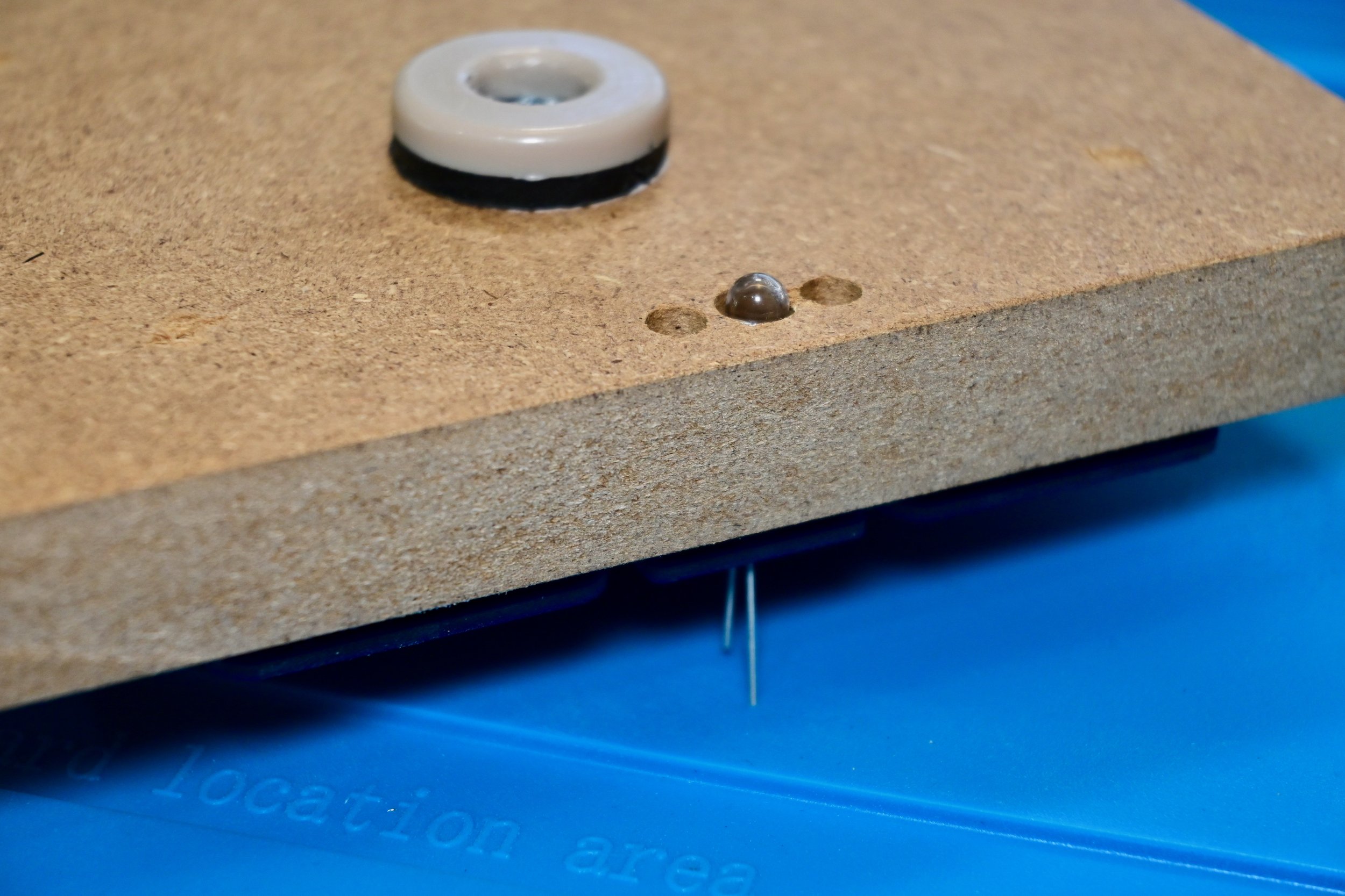
Align the LED so that about 1mm of its curved lens sticks out of the bottom of the robot platform.

The holes you drilled for the floor sensor components should be lined up with their circuit board pads.

Carefully solder the LED leads on the top of the CHRP4 circuit board.

Insert the IR floor LED leads into the circuit board pads for D6 from the bottom of the robot platform. The long LED lead goes into the D6 square pad on CHRP4.

Mount the Q1 and Q2 phototransistors the same way. Ensure their long (emitter) leads go to the square pads on CHRP4, align them to be the same height as the LED, and solder them into place.
Step 2 - Wire the motors and battery pack to the screw terminal strip

Strip approximately 10mm (3/8”) of insulation from the ends of the battery pack wires and tin the wires with solder.
Strip about 3mm (1/8”) of insulation from each of the four motor wires and tin all the ends.

Carefully bend the motor terminals upwards slightly and lightly tin the motor terminals (try not to heat them for too long).

Insert the tinned end of one motor wire into one of the motor terminals, and solder it into place. Repeat these same steps for each of the four motor wires.

Measure and cut the motor wires to an appropriate length to reach the terminal strip, and then strip and tin 10mm of the end of each motor wire.

Connect the wires to the terminal block. From left to right, the wires will be: the battery positive wire (red), the battery negative wire (black), the two left motor wires, and the two right motor wires. Insert the bare wire until it stops and tighten the screw to keep it in place.
Pro tip: ensure the wire insulation goes right up to the solder connections on the motors and to the shell of the screw terminal block to minimize the chance of wiring shorts!

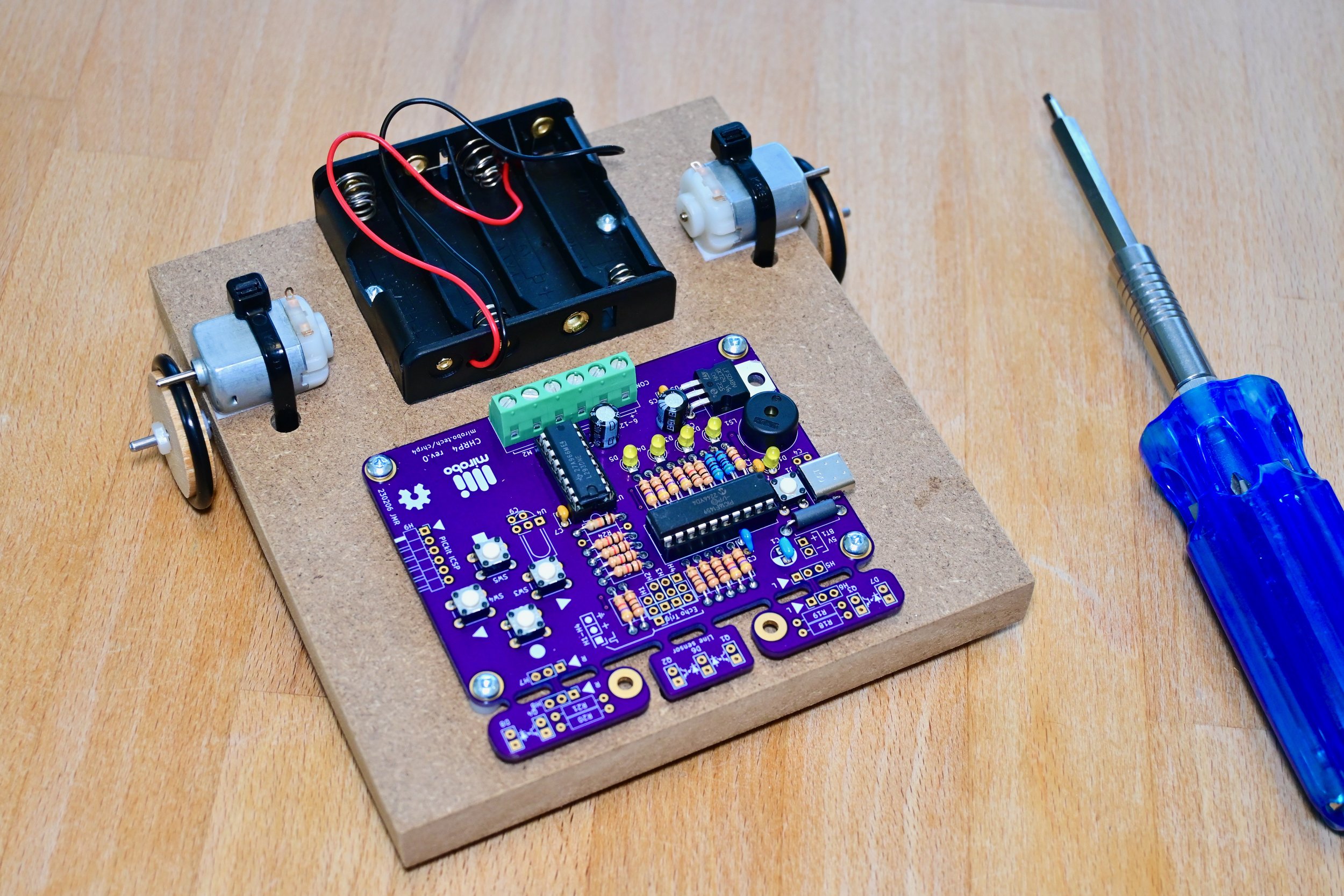
Ready to go! A completed CHRP4 line-following robot built on the simple robo platform. Where will this road take you?