
PIANO-3 Introductory Learn-to-Solder Kit
When Microchip released their tiny PIC12F1840 microcontroller with built-in touch sensor capability, we wanted to do something fun with it! PIANO-3 is our newest touch piano circuit – a mini pocket piano capable of playing eight notes and doubling as a metronome. This latest version features a grand piano-shaped circuit board design with fewer electronic components, making PIANO-3 a simple learn-to-solder kit for beginner electronic hobbyists.
The microcontroller that controls PIANO-3 is pre-programmed with both the piano and metronome functions so no programming knowledge is required is required. Just follow the step-by-step assembly instructions, below, to assemble your circuit and start to play!
Tiny piano, grand possibilities
PIANO-3 follows our simple projects, big impact philosophy to help you take your learning further.
PIANO-3 is controlled by a tiny computer-on-a-chip known as a microcontroller. And, while you don’t need to know anything about programming microcontrollers to build and use your PAINO-3 circuit, it does include a PIC-kit ICSP (In-Circuit Serial Programming) header allowing advanced users to reprogram its PIC12F1840 microcontroller (requires Microchip Technology’s MPLAB X software, and a PICkit-4 or PICkit-5 programmer). The full PIANO-3 source code is provided on our Github page to help you take your learning even further.
PIANO-3 details
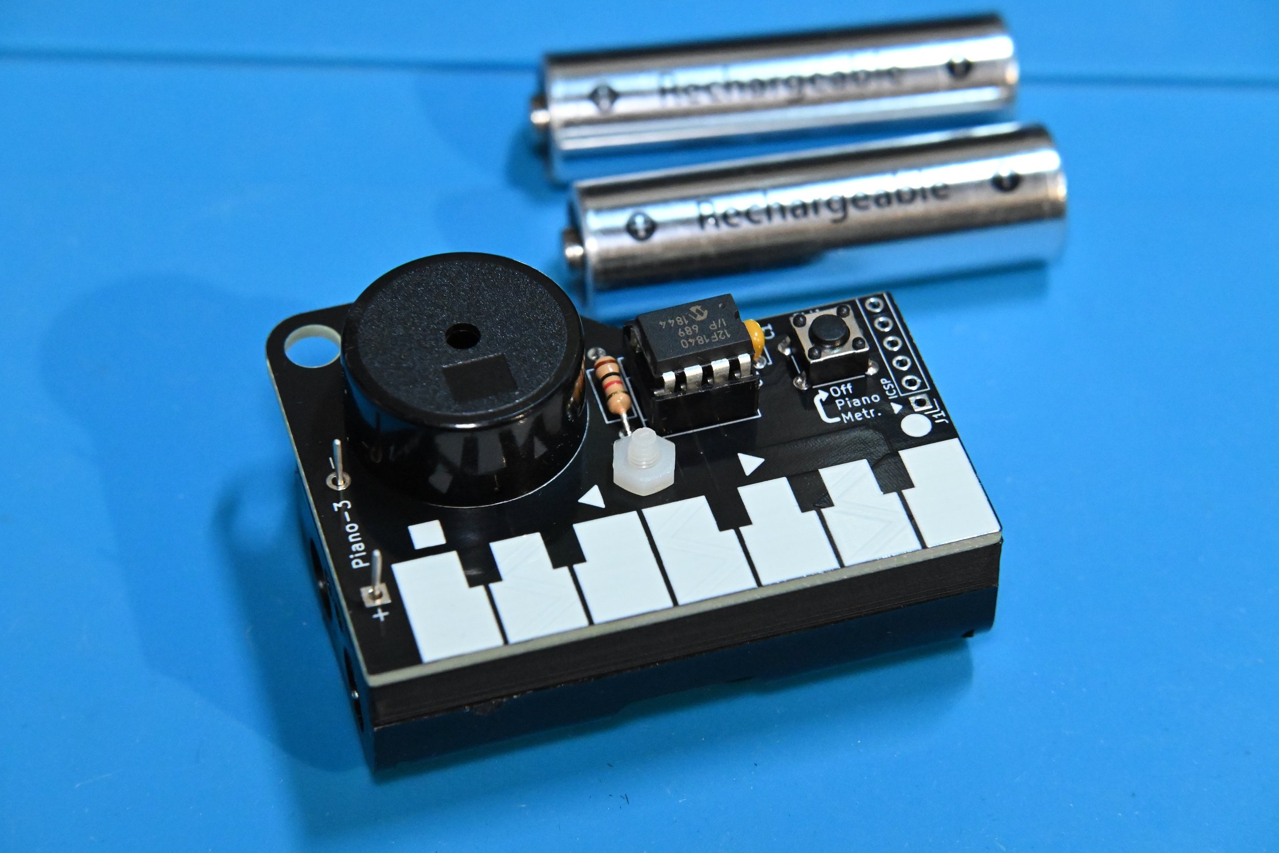
PIANO-3 runs for weeks on two commonly available AA batteries. As a piano, it plays the eight notes of the C major scale, from a note known as C5 (a frequency of 523.25Hz) to note C6 (1046 Hz).
PIANO-3 also doubles as a metronome, with selectable 40 - 240 beat per minute (BPM) rates as well as 1 - 8 selectable beats per measure played using different up- and down-beats. All of the components required to assemble PIANO-3 are included in the kit, except for the two batteries and the 6-pin header needed for advanced users to reprogram their PIANO-3.
Getting ready to build your PIANO-3
Gather all of the required tools and equipment before assembling PIANO-3. We recommend:
a soldering iron with a fine tip meant for soldering electronic parts, and a damp soldering sponge to clean the soldering iron tip (If you’re new to soldering, check out this excellent Soldering is Easy comic.)
electronic solder with a no-clean, or water soluble flux
small diagonal cutters or low-profile shear cutters to trim long component leads after soldering
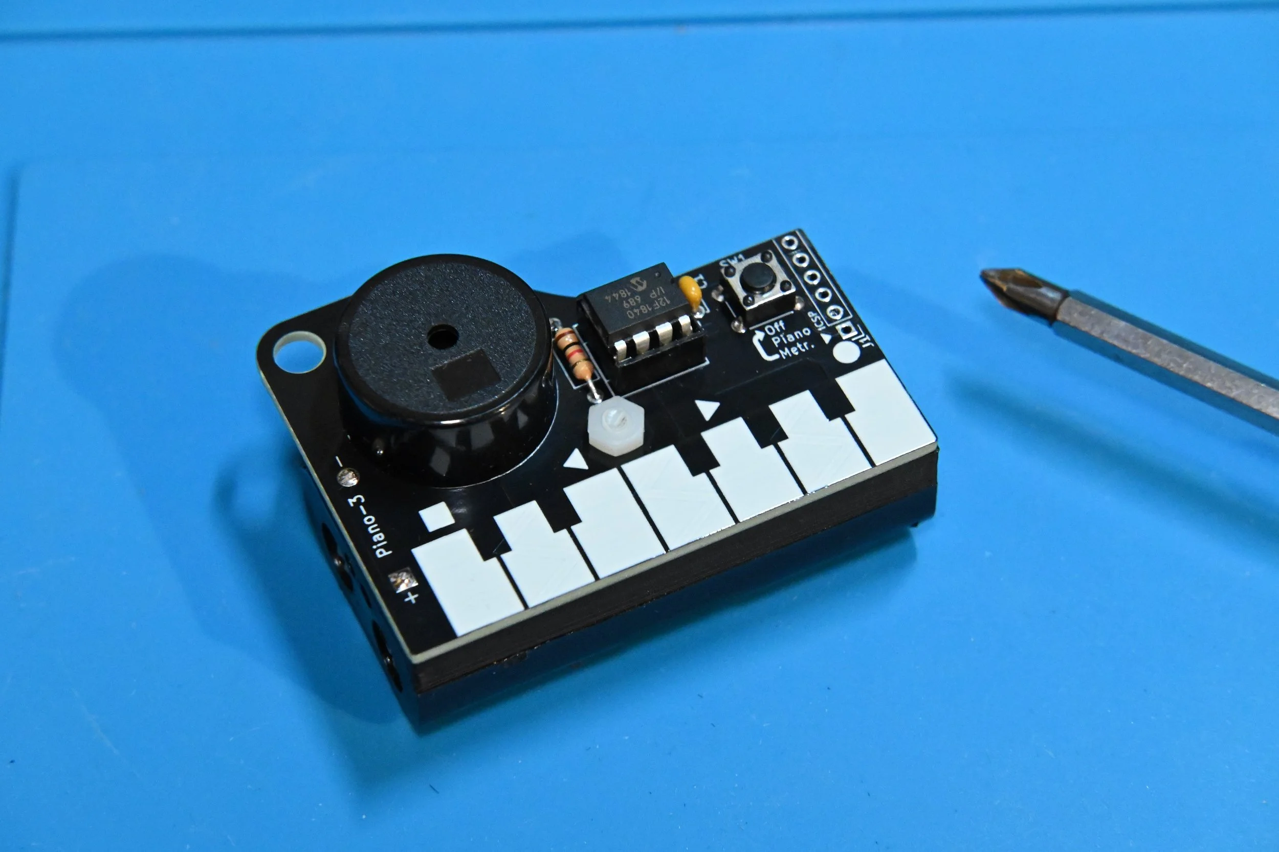
a small Phillips screwdriver and needle-nose pliers to attach the battery holder
Step 1 - Check your components
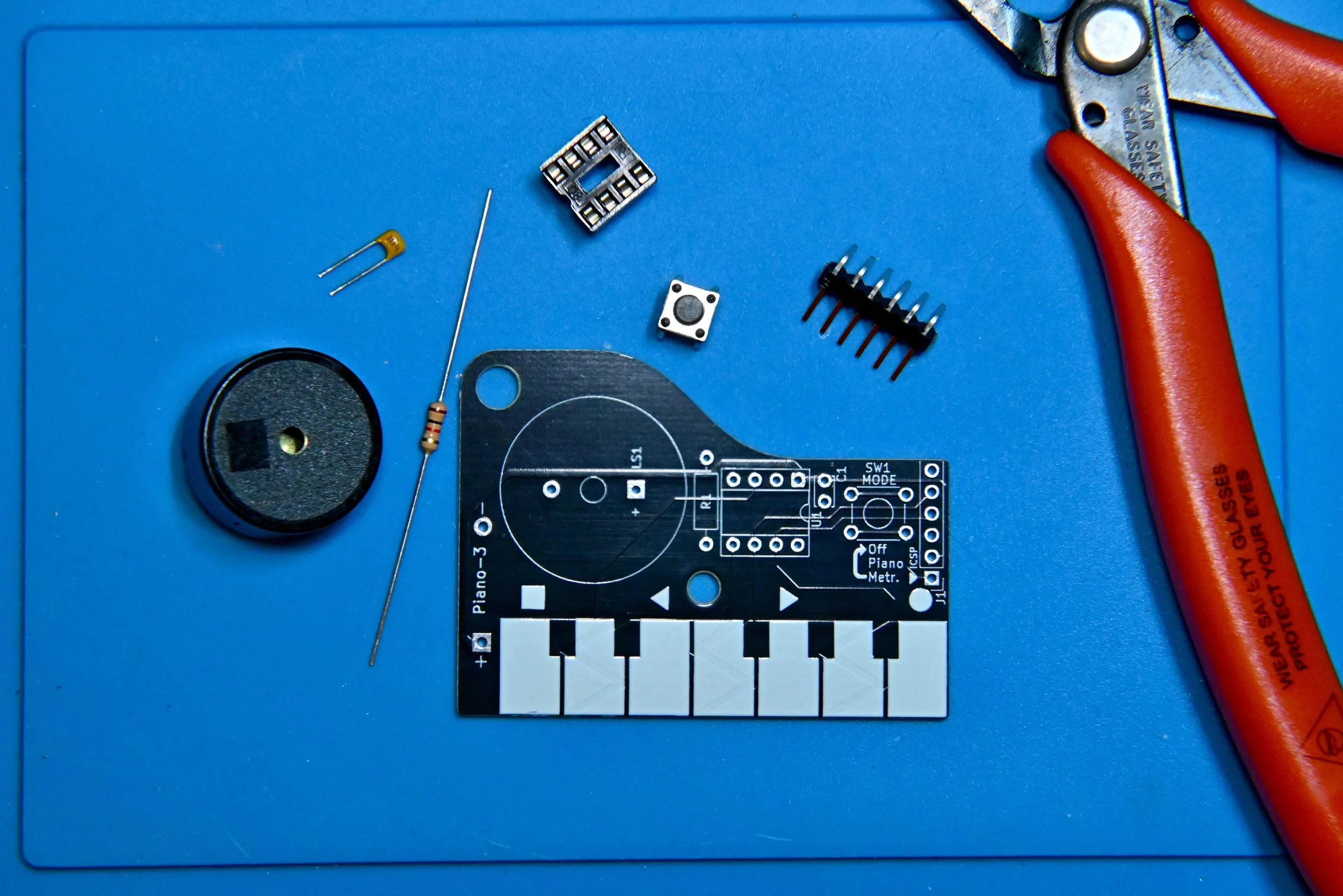
First, confirm that you have all of the required and optional components in your kit. You can use the PIANO-3 schematic diagram to help identify each component and see how they are connected to make the circuit.
PIANO-3 circuit components
1 - PIANO-3 PCB (Printed Circuit Board)
1 - 1.0kΩ, 1/4W resistor (colour code: brown, black, red, gold)
1 - 6mm pushbutton
1 - 100nF ceramic monolithic capacitor (numeric code: 104)
1 - piezo beeper (non-polarized)
1 - 8-pin DIP (dual-inline package) IC (Integrated Circuit) socket
1 - PIC12F1840 microcontroller
1 - PCB-mount dual AA battery holder
1 - 3D-printed PCB spacer
1 - M3 nylon screw
1 - M3 nylon nut
PIANO-3 Operation
PIANO-3 is a simple beginner circuit with two main modes of operation: piano mode, metronome mode, and a third off mode. Briefly pressing and releasing the SW1 MODE pushbutton changes PIANO-3’s operating mode.
Piano mode
When the batteries are first installed, PIANO-3 starts up in piano mode. Touching each of the white keys will play the first seven notes of a C major musical scale. Touching both the first and last keys at the same time will play the eighth (highest) note of the scale. From piano mode, press and release pushbutton button SW1 to switch to metronome mode.
Metronome mode
The shape symbols above the keys indicate the metronome function of each key.
Square - starts and stops the metronome beats. PIANO-3 remembers the last used speed and beats per measure setting until the batteries are removed.
Arrows - decrease or increase the metronome beats per minute rate in steps of 5, from 40 to 240 BPM.
Circle - cycles through 1 to 8 beats per measure. At 1 beat per measure the metronome beats at a single pitch. Increasing the beats per measure makes a higher pitch first beat followed by lower pitch beats to complete the measure.
From Metronome mode, press and release pushbutton SW1 to switch to off mode.
Off mode
Off mode isn’t really off, but it is a low-power nap mode for PIANO-3’s microcontroller. It’s best to remove the batteries if your PIANO-3 circuit will not be used for an extended period of time.
Step 2 - Solder the circuit board components
Soldering electronic components in order of smallest to tallest typically makes circuit board assembly easier, so that’s how the steps will lead you through building PIANO-3.
Component orientation does not matter for the resistors, pushbutton, capacitor, or piezo beeper in this circuit.
Important: don’t race ahead and install the battery holder until the next set of steps, below.
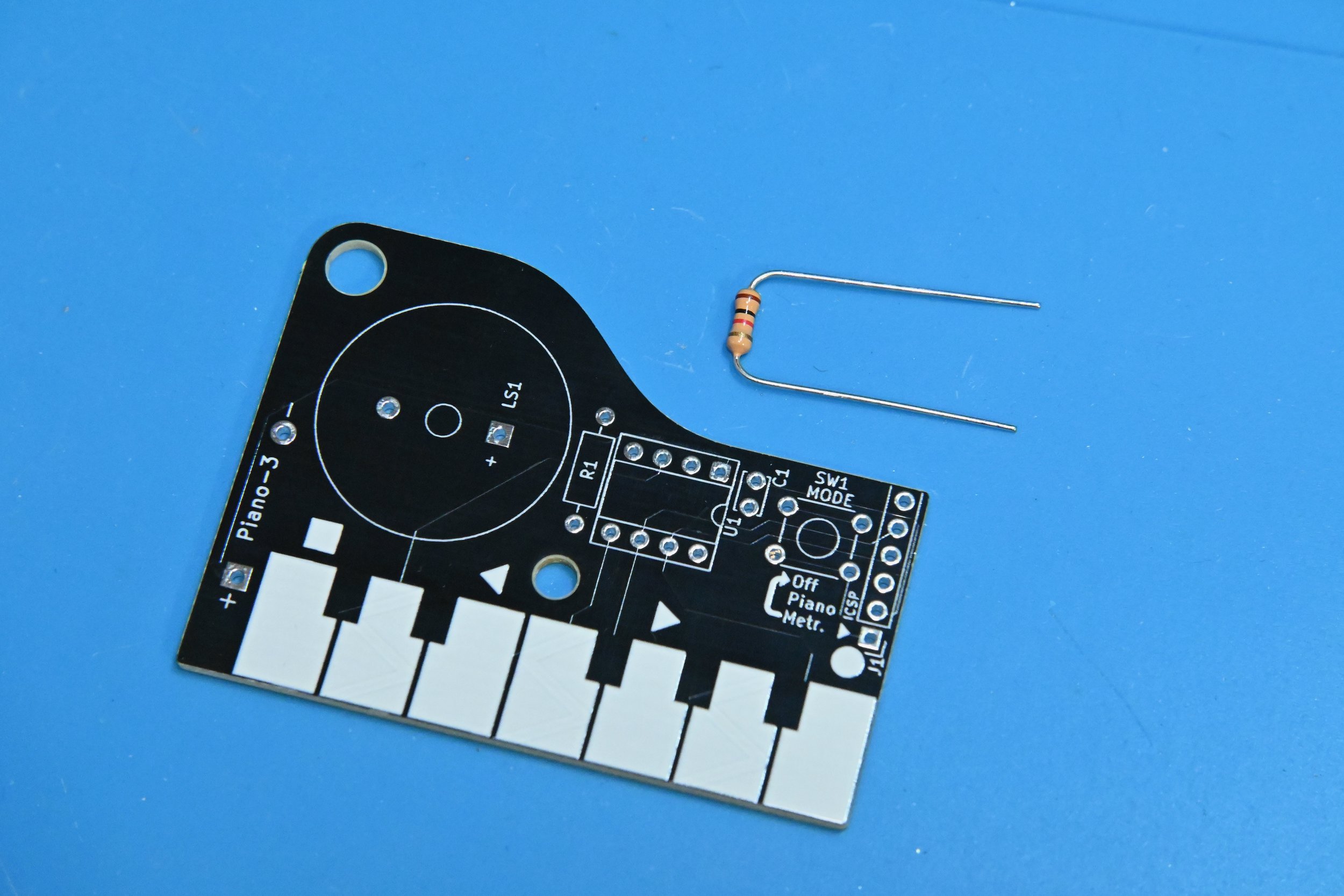
2.1 Start by bending the wire leads of resistor R1 into a u shape. Then, insert one lead through each of the circular metal pads at either end of rectangular resistor symbol R1, so that the resistor body is sitting on top of the R1 rectangle.
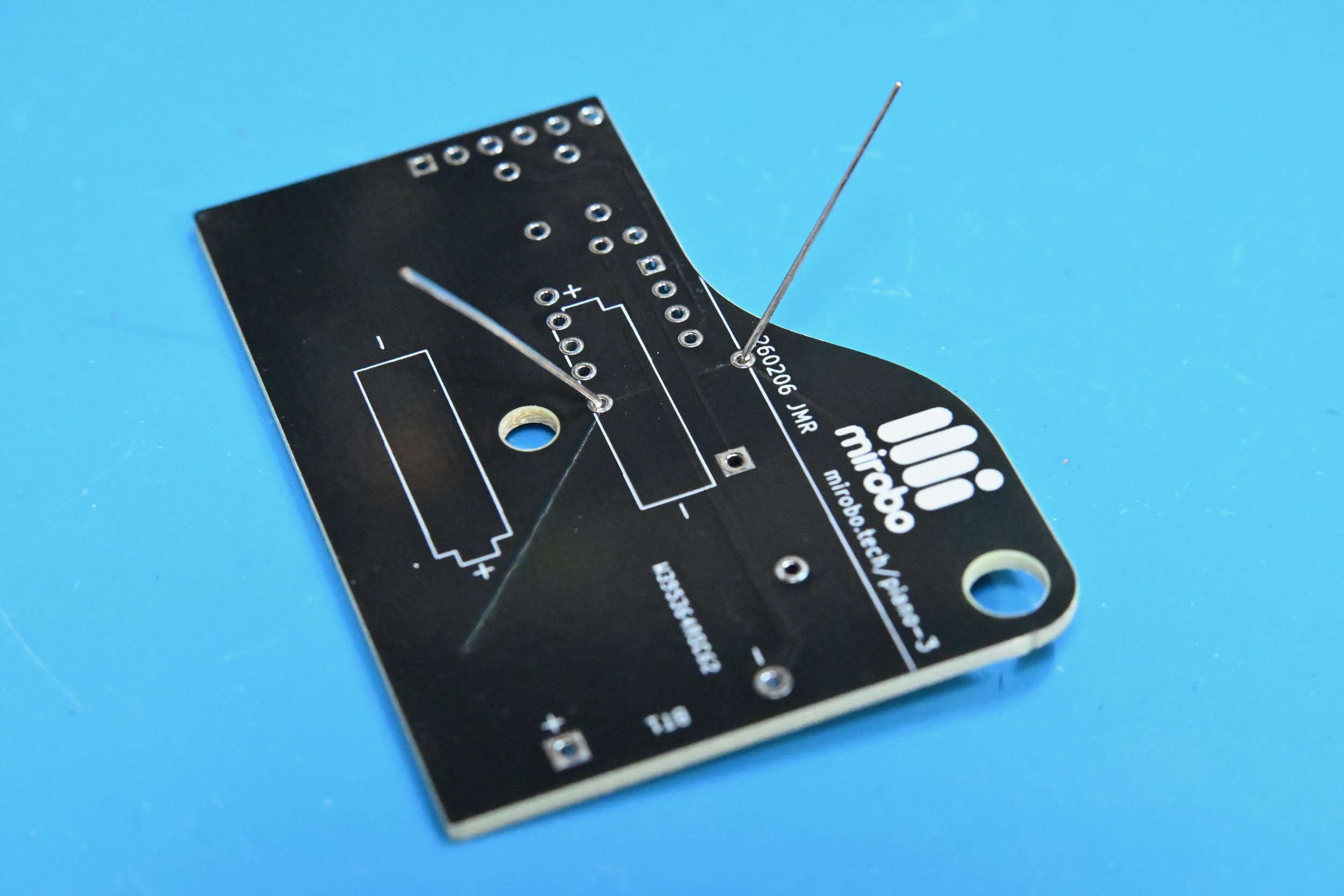
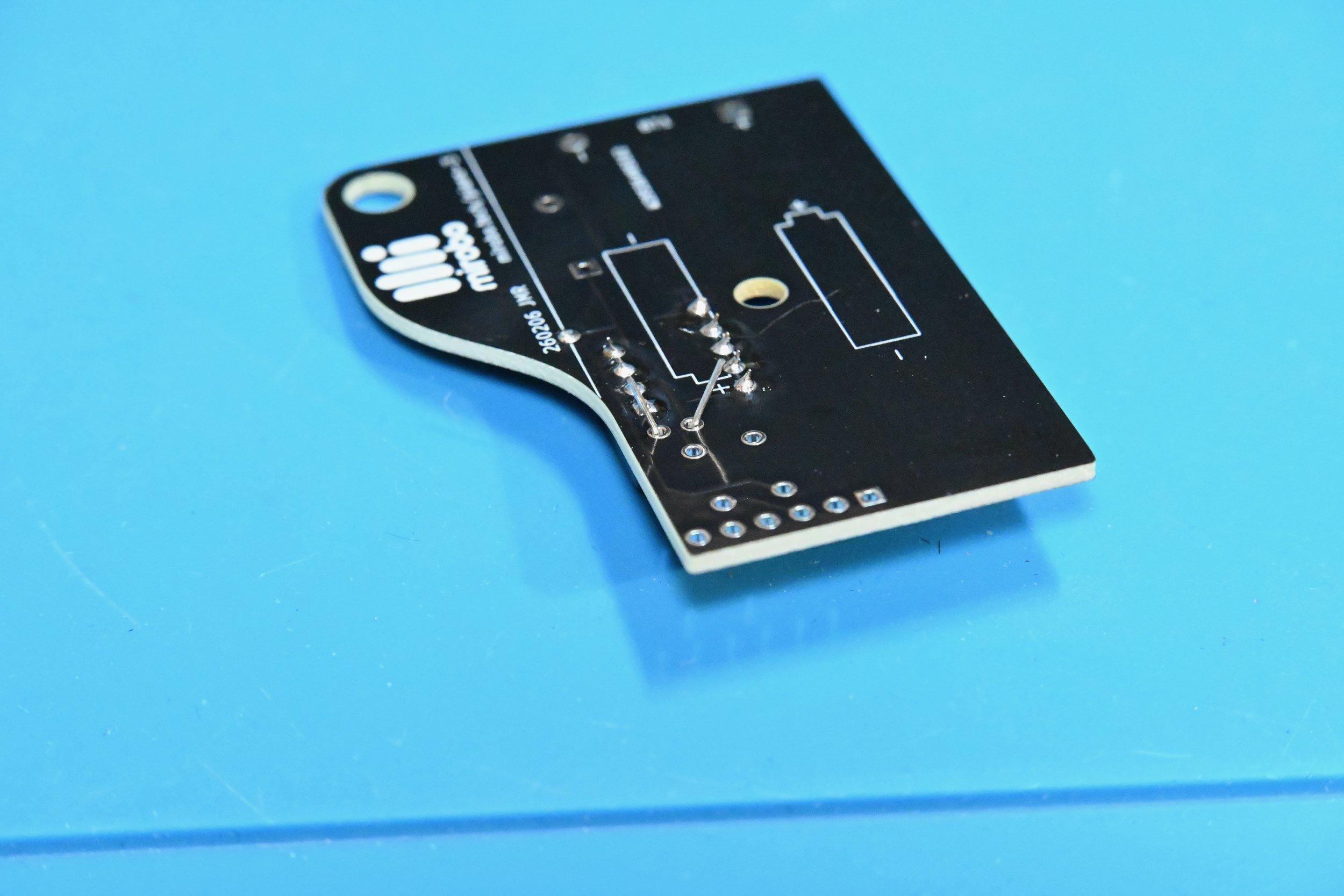
2.2 Flip the circuit board over and, while holding the resistor body against the circuit board, gently spread the resistor leads a little bit. Doing this helps to keep the resistor from lifting off the circuit board, but don’t bend the leads too far – doing that makes soldering more difficult.
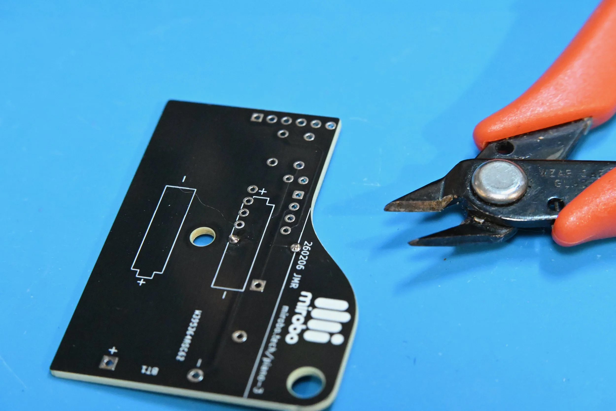
2.3 Solder each resistor R1 lead to its pad using a minimum of solder. Heat both the pad and the resistor lead at the same time, and apply solder to join them together. Cut the leads right above the solder connection. (See Soldering is Easy for details.)
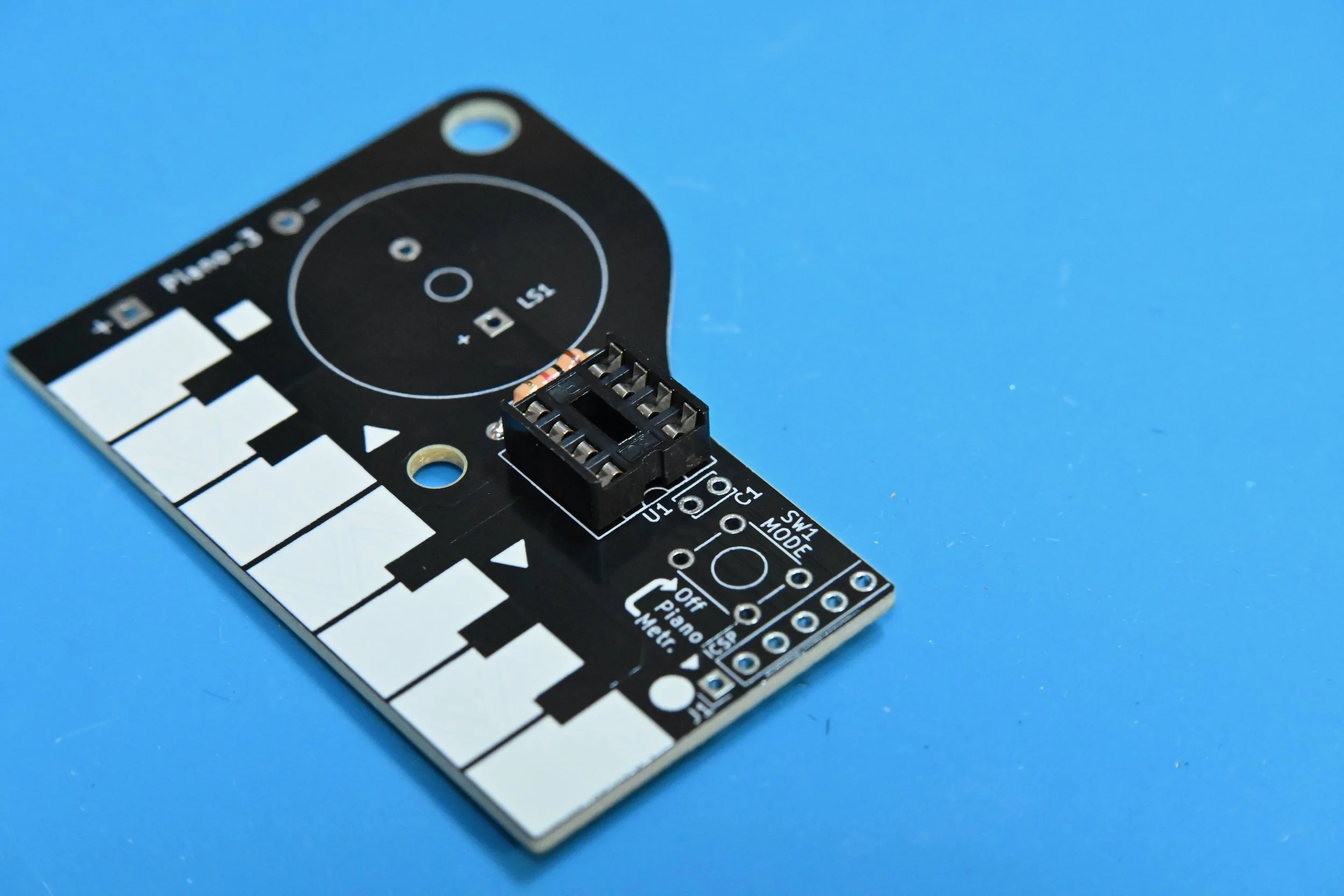
2.4 Align the small notch at one end of the IC socket with the painted notch (near the U1 marking) on the circuit board. Carefully insert all 8 leads of the IC socket into their pads in the circuit board, making sure that all pins go through their pads to the bottom side of the board. Solder only one pin on each side of the IC socket first – then flip the board over to make sure that the socket is straight and level. If the socket isn’t flat against the board, re-heat the pin on the high side of the socket while gently pushing the socket down to align it flat on the board.
2.5 Finish soldering all of the rest of the IC pins after the socket is level – they’re short enough that they don’t need to be trimmed after soldering.
Next, insert the small capacitor into C1 beside the IC socket. While holding the capacitor in place, flip the board over and bend its pins on the bottom – exactly as you did with the resistor. Solder the two capacitor leads, and trim them just above the solder connection.
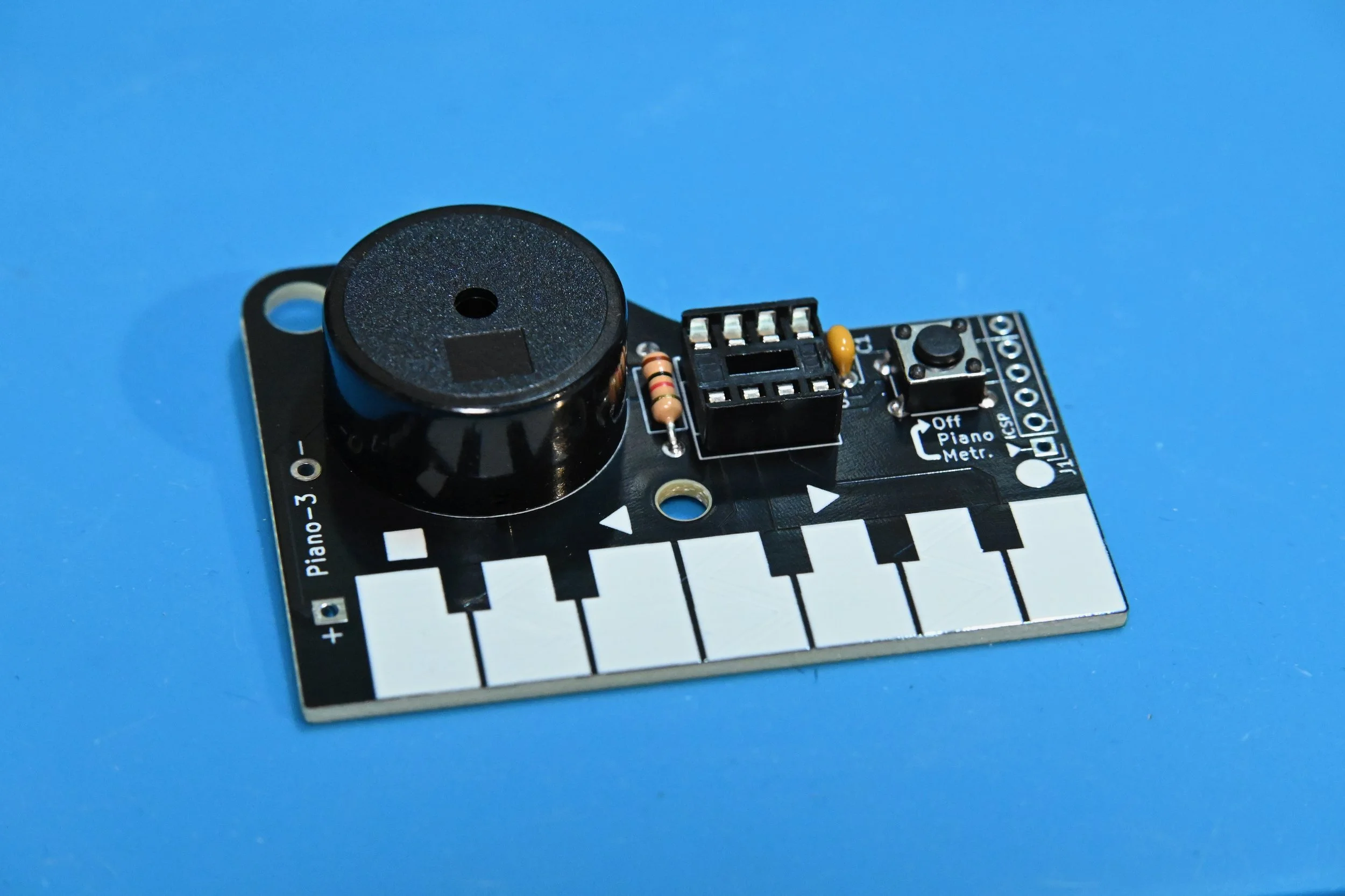
2.6 Insert pushbutton SW1 into the circuit board (you may have to apply pressure to snap its bent pins into their pads). Solder all four pushbutton pins.
Insert piezo speaker LS1 into the circuit board and hold it as you flip the board over. Hold the PIANO-3 circuit level as you solder each speaker pin into place.
Inspect the circuit and soldering
After soldering these parts into place, carefully inspect all of your solder connections. Fix any connections that don’t have enough solder joining the component leads to their PCB pads by re-heating them and adding a small amount of fresh solder. Fix any large solder blobs or shorted connections by repeatedly cleaning the soldering iron tip to wipe away excess solder, and applying the tip to the solder blob to remove some solder. (Or, use a solder sucker or desoldering braid if one is available.)
Clean the circuit board
If you assembled your circuit using solder formulated using a no-clean flux, you are ready to proceed to the next step.
Important: Solder flux residue will cause problems with capacitive piano key sensing, and may lead to corrosion and unreliable operation in the future. Research the type of flux contained in your solder, and use the type of flux remover recommended by the solder manufacturer to remove the flux residue. If your solder contains a water-soluble flux, simply rinse the bottom of the circuit board in warm running water to remove the flux residue (stickier residue can be removed by brushing it under running water with an old toothbrush). Cover the hole in the piezo speaker with your finger to prevent water ingress into it, and shake off any excess water, before drying the board.
Allow the circuit board to dry completely after cleaning before proceeding to the next assembly steps.
Step 3 - Testing and final assembly
Important - do not solder the battery holder until your circuit has been tested! Once the battery holder is soldered onto the PIANO-3 circuit, it will be difficult to fix it without potentially damaging the circuit board or the battery holder.
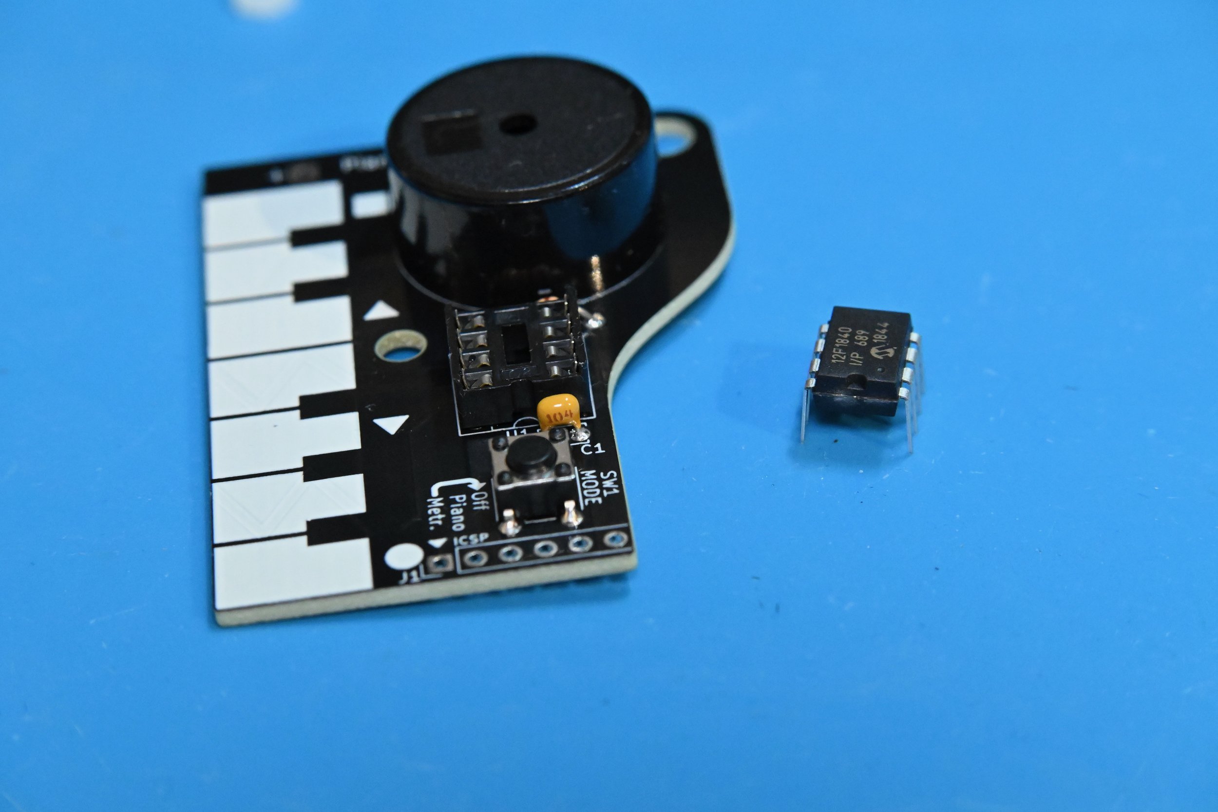
3.1 After the circuit board has been cleaned and dried, straighten the pins of the PIC12F1840 microcontroller so that they are facing straight down instead of angling slightly outward. Align the notch or dot on the microcontroller with the notch on the IC socket and press its pins firmly into place in-between the metal contacts of the receptacles in the IC socket.
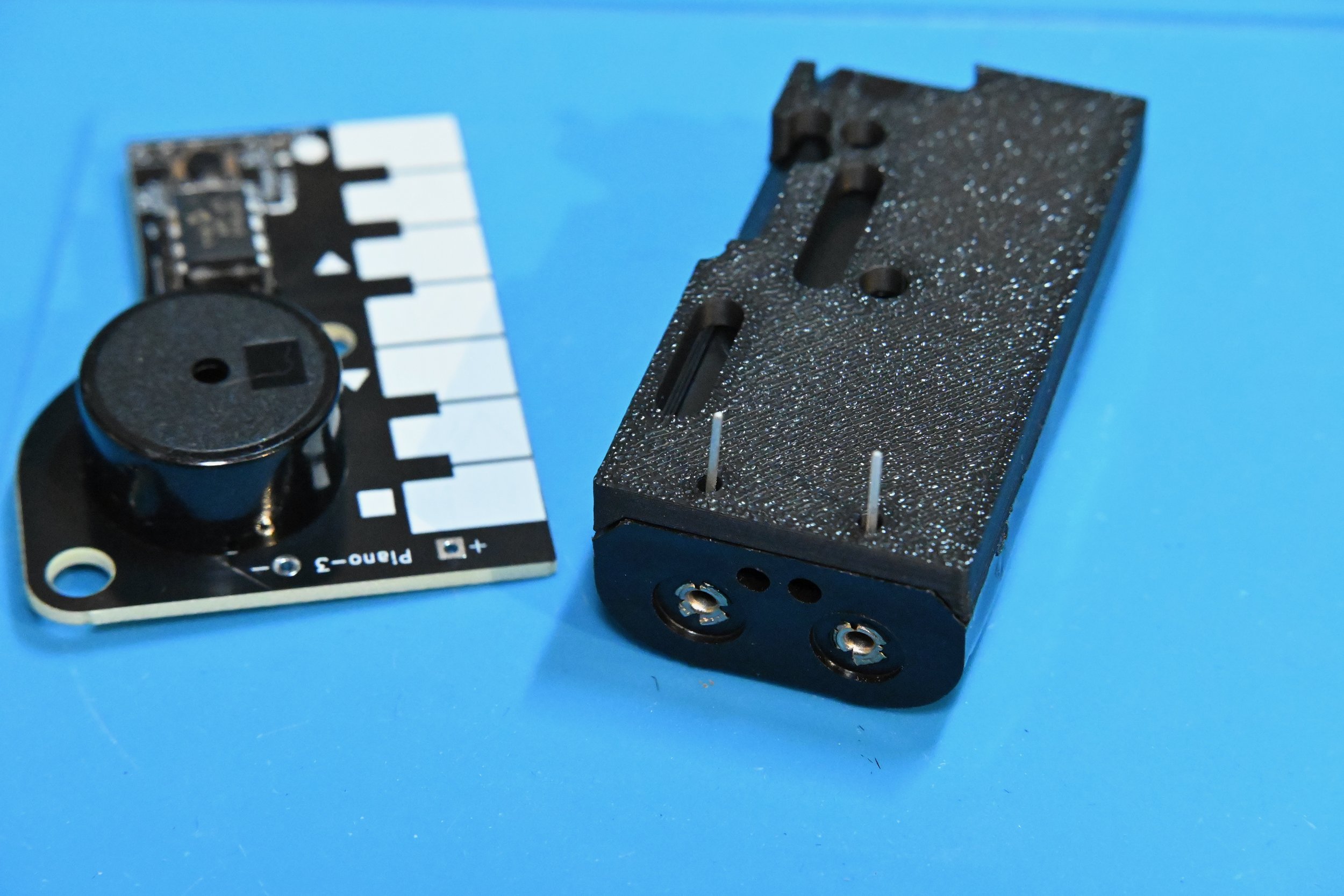
3.2 Inset two AA batteries into the battery holder. Push the pins of the battery holder through the 3D-printed spacer, and then into the + and - pads on the bottom of the PIANO-3 circuit. (The two small bumps on the spacer fit into holes in the battery holder.) DO NOT SOLDER THE BATTERY HOLDER IN YET!
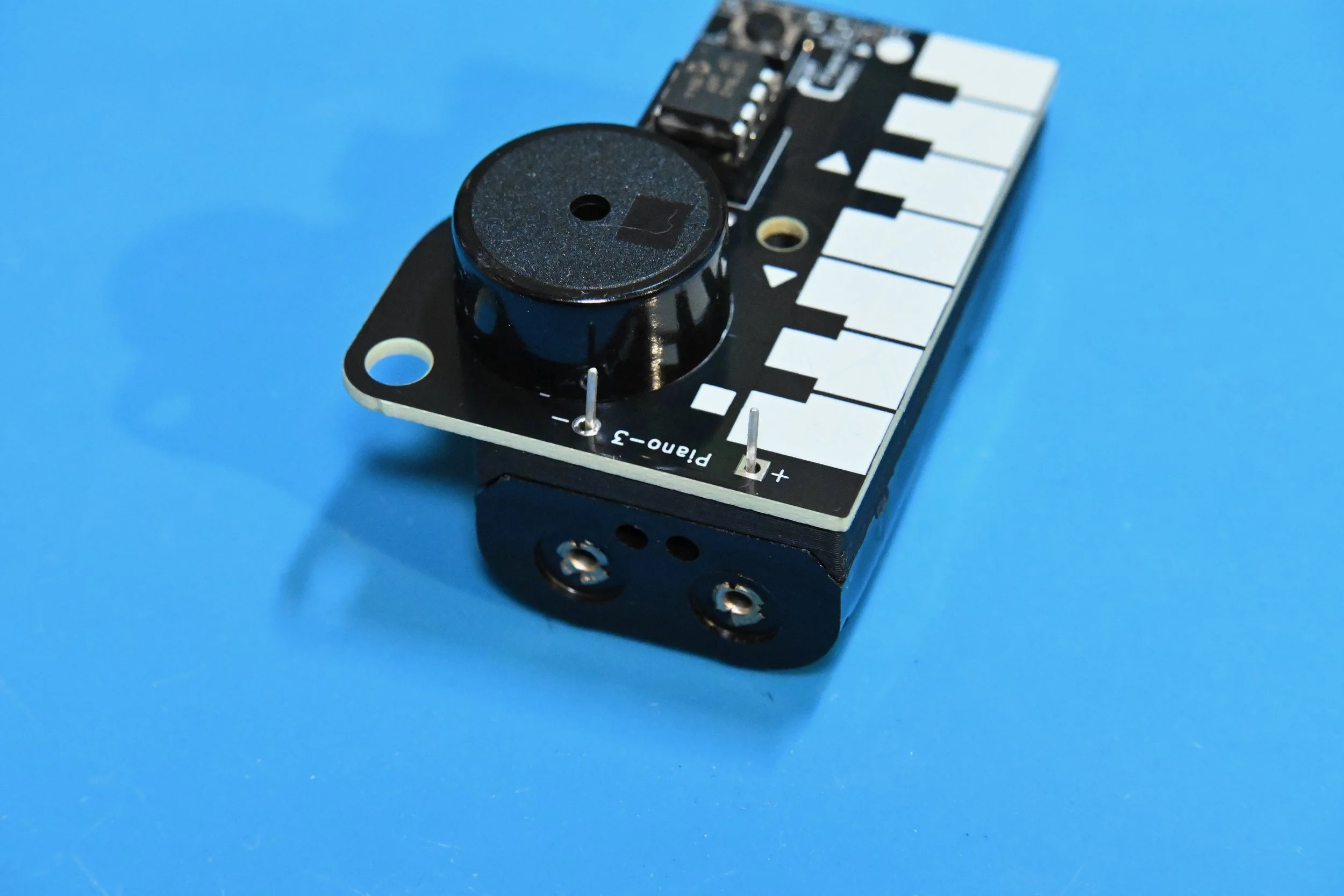
3.3 Test the PIANO-3 circuit by gently pushing or holding the pins of the battery holder against the metal pads of the PIANO-3 circuit to power it, and then tapping each key to play every note. Next, test the pushbutton to switch the PIANO into metronome mode (it will make repeated ticks). If every note plays and the pushbutton works, you’re ready to attach and then solder on the battery holder.
If one or more of the notes do not play, remove the battery holder and check for poor or incomplete solder connections on the bottom of the IC socket. Re-solder any bad connections and then test the PIANO-3 circuit again.
3.4 After testing the circuit, remove the batteries and Insert the M3 nylon screw through the battery holder and up through the hole in the circuit board. Add the M3 nylon nut on the top of the circuit board, and tighten the screw to attach the battery holder to the PIANO-3 circuit Turn the screw just until it starts to become tight. Do not over tighten it! The excess length of the nylon screw can be cut off using shear cutters or a hobby knife.
Finally, solder the battery holder leads onto the metal pads on the top of the circuit board, and clean away any solder flux from the battery holder solder pads.
That’s it! Your PIANO-3 is now completely assembled and ready to play! Reinsert the batteries and read over the operating instructions at the top of this page to learn how it works. Remember to remove the batteries if it will not be used for an extended period of time.
PIANO-3 Resources
PIANO-3 Schematic
PIANO-3 Source Code