
How mirobo programs are structured
If you’re new to C language programming you may not be familiar with the multiple-file structure of typical C programs. Even if you are familiar with C language programming, this page will describe how mirobo programming projects are structured. Although these explanations apply specifically to mirobo projects, you may find that many of these concepts also apply to other projects and programming languages.
Programs are split into multiple files
While a C language program can be written in a single source code file, most C programs are actually split into multiple files. For beginner programmers, one advantage of breaking a program into multiple files is that it simplifies the main source file by reducing the amount of extraneous code it contains. This enables beginning learners to more easily focus on the important or relevant parts of the program code as they learn to program, while the more potentially confusing initialization code and lengthy definitions essentially are kept hidden from view in other files. Obviously, needing to tie all of these separate parts into a cohesive program at some point adds additional hurdles for beginners to overcome.
Another advantage of splitting a program into multiple files is to promote code modularity and program code re-use. Programs can be written in such as way that some of the exact same code files can be used across different circuit board revisions, or in entirely different microprocessors, while other program files are designed to manage the differences, shortening software development time significantly.
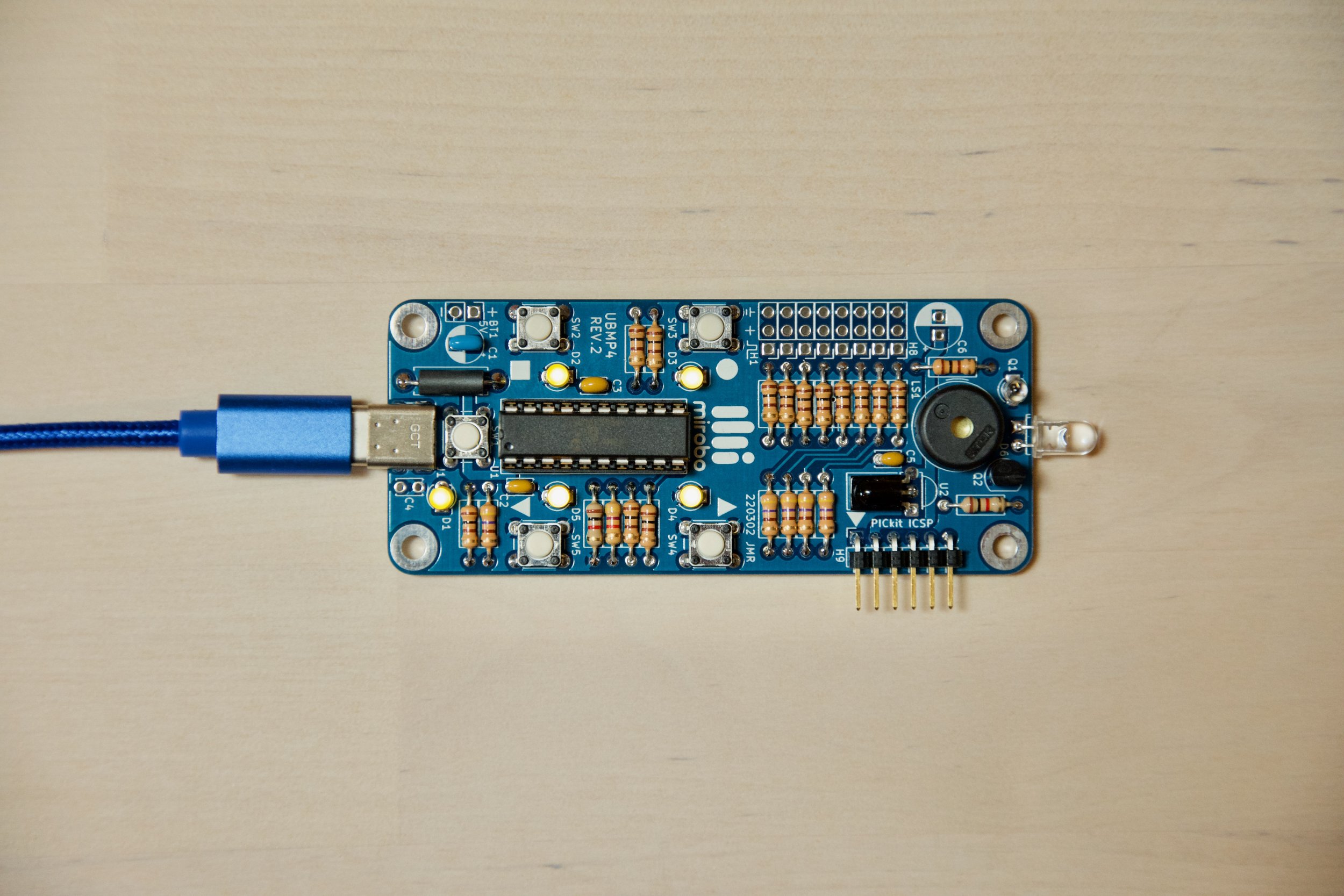
All of the individual program files for a PIC microcontroller program are combined in an MPLAB project – projects contain all of the program files, as well as all of the microcontroller settings required to program a circuit to do something useful.
The four files in every mirobo project
Each mirobo project is composed of at least four files: one main user program file, and three additional support files (these will remain mostly unchanged for every programming project that uses the same circuit board or hardware devices). Some of the later introductory programming activities, as well as some of the more advanced programming activities, contain additional files that are used to add new features or functionality to the programs.
The main program file and two of the other three files are source code files. Source code files contain program instructions for the microcontroller to run, and their filenames end with a .c file extension. The fourth file is a header file, and its filename ends with a .h file extension. Header files contain information that is necessary to support the source code files.
The table below summarizes the functions of each of the four files that make up the CHRP4-Intro-1-Input-Output.X MPLAB programming project – the first introductory programming activity for the CHRP4 circuit board:
| CHRP4 Project File | File Description |
|---|---|
| CHRP4.h | A circuit board header file containing hardware definitions and function prototypes which make it easier for the user to program the circuit. |
| CHRP4.c | A circuit board function file containing the C language source code of functions used to initialize the microcontroller and enable the use of the I/O devices. |
| Intro-1-Input-Output.c | The main C language program source code file containing the main( ) function and the major parts of the user's program code. |
| PIC16F1459-config.c | A processor configuration file used to enable, disable, or select specific hardware features of the PIC16F1459 microcontroller. |
It’s important to note that the circuit board header and circuit board function files are specific to the circuit board they are designed to support. In this case these are the CHRP4.h and CHRP4.c files, which have been created specifically to support programs running in the CHRP4 circuit. Similarly, programming projects created for the UBMP4 circuit would contain the UBMP4.h and UBMP4.c files instead, which are also identically named for the circuit they are designed to support. Having files created specifically to support each circuit in a project means that when a program needs to be shared or moved from one circuit board to another, the move can often be accomplished by simply substituting the new circuit board header and function files in the new programming project.
The Intro-1-Input-Output.c file contains the main user program for this programming project. It is considered the main program file because it contains the main( ) program function, which holds the main program code for all of the introductory activities. Except for one line of program code, the contents of this file are identical for both the CHRP4 and UBMP4 circuits.
The PIC16F1459-config.c file is a microcontroller configuration file. Each microcontroller has some software-controlled configuration settings that control certain hardware features during programming, and this file contains all of that information. Switching to a different microcontroller could be accomplished by substituting a different microcontroller configuration file for this one.
Now that we have a better understanding of how these four files enable programmers to create more modular projects, let’s explore the contents of each file to get an idea of how they work together to make a single program.
C Language Concepts
You might be new to C, or new to programming in general – don’t worry, we’ll take it step-by-step. Here are some important terms and other things you should know to get started:
C programs are often composed of more than one source code file.
most C programs include files containing source code instructions (with a .c file extension), as well as files containing directives that might normally reside at the top, or head, of a program, called header files (.h file extension).
each C program has to include one file containing the main( ) function, which is the start of the program and contains the main body of the program inside its braces { }. In this program, the main( ) function appears as:
    int main(void)
    {
         ...
    }
blocks of C statements making up structures or functions are grouped inside curly braces – { }
C statements or expressions are terminated by a semicolon ( ; ) – think of it as being similar to a sentence that is ended with a period.
statements inside curly braces are indented for readability, but the type and amount of spacing used for indenting doesn’t matter to the compiler – consistent spacing just makes the code easier to read and debug.
single-line code comments are ignored by the compiler and start with double slashes – //
multi-line code comments start with /* and end with */
These examples are based on the first introductory programming project for the CHRP4 circuit board. The contents of the equivalent files for other circuits will be similar, though not identical, to this one, and all of the same concepts will apply.
The circuit board header file
The CHRP4.h header file is used to provide important information about the CHRP4 circuit board to the C compiler, making it easier for the user to utilize features of the circuit board. If you open the actual CHRP4.h header file (or the header file for any mirobo circuit) in the code editor, you will see that it is divided into two distinct sections. The first section is used for I/O (input and output) device definitions, and is further sub-divided and organized by the number or types of I/O ports or devices that are available to the microcontroller. The second section is used to declare function prototypes. Let’s get a better understanding of each.
Header I/O definitions
The first section of the header file (following the comments at the top of the header) is mainly I/O pin definitions created using C compiler #define directives. A #define directive allows programmers to define an alias to represent a number or expression. For example, the very first definition in the extract of the CHRP4.h file shown below defines the alias SW1 to represent the port pin PORTAbits.RA3 – the physical port register address of the PIC16F1459 microcontroller pin connected to pushbutton switch SW1 on the CHRP4 circuit board.
// PORTA I/O pin definitions
#define SW1         PORTAbits.RA3   // SW1/PROG/Reset (MCLR) pushbutton input
#define BEEPER      LATAbits.LATA4  // Piezo beeper (LS1) output
#define	LS1         LATAbits.LATA4  // Piezo beeper (LS1) output
#define D1          LATAbits.LATA5  // LED D1/RUN LED output (active-low)
#define LED1        LATAbits.LATA5  // LED D1/RUN LED output (active-low)

// PORTB I/O pin definitions
#define H1IN        PORTBbits.RB4   // External I/O header H1 input
#define H1OUT       LATBbits.LATB4  // External I/O header H1 output
#define SW2         PORTBbits.RB4   // Pushbutton SW2 input

#define H2IN        PORTBbits.RB5   // External I/O header H2 input
#define H2OUT       LATBbits.LATB5  // External I/O header H2 output
#define SW3         PORTBbits.RB5   // Pushbutton SW3 input
#define TRIG        LATBbits.LATB5  // SONAR module Trigger output
  .
  .

  // ADC (A-D converter) input channel definitions
#define AN6         0b00011000      // A-D converter channel 6 input
#define ANQ1        0b00011000      // Floor sensor Q1 analogue input (Ch6)
#define ANQ3        0b00011000      // Floor sensor Q3 analogue input (Ch6)
#define AN7         0b00011100      // A-D converter channel 7 input
#define ANQ2        0b00011100      // Floor sensor Q2 analogue input (Ch7)
#define ANQ4        0b00011100      // Floor sensor Q4 analogue input (Ch7)
There are a few interesting things to note in the sample extracted from the CHRP4.h header file, above.
First, multiple aliases can be defined for the same entity. The next two definitions after the definition for SW1 define both BEEPER and LS1 as aliases for the I/O port pin LATAbits.LATA4. Why does it need two aliases? LS1 is the official reference given to the piezo beeper element on the CHRP4 schematic, but the word BEEPER is potentially more meaningful to a programmer, so both have been defined. The next two definitions are similar – D1 is the schematic reference of one of the LEDs on the CHRP4 board, but LED1 was the reference name used for a part with the exact same function on a prior board revision. In order to make it easier to port older programs to the new board, as well as to provide more context for the specific type of diode being used (LED vs. D), both aliases were defined in this new header file. Either one can be used in a program to refer to LED D1.
Next, you may have noticed that all of the hardware reference names are spelled in ALL CAPS. This is not strictly necessary, but follows common C conventions of capitalizing the names of hardware constants, and makes these hardware aliases distinct from other variable and function names when seen together in a program.
Last, note that the entities being defined can be very diverse – the #define directive is parsed by the C language pre-processor at compile time, and it can be used to define a wide variety of constants and expressions. (Microchip’s MPLAB® XC8 C Compiler User’s Guide for PIC® MCU document has all of the details you would ever want to know about C programming for the PIC microcontroller.) The following example definitions, all of which are found in the CHRP4.h file, define a hardware port address, a binary constant, and a decimal constant, respectively:
#define H1IN PORTBbits.RB4
#define AN6 0b00011000
#define _XTAL_FREQ 48000000
It should now be clear that the use of these I/O pin definitions can help to make both programming and debugging tasks faster and easier for a user programming this circuit. Pin definitions such as SW1 are much shorter to type than their port addresses, and are also more meaningful given that they represent the real names of devices on the circuit board. Programmers can quickly refer to the on-board device names when crafting their programs, and the header definitions take care of the actual port details.
Header function prototypes
The second section of the CHRP4 header file contains function prototypes – single line statements used to define function names and variable types that will be used by other parts of the program code.
The first function prototype found in the header file is shown below. The example begins with a comment block (inside the /* and */ characters) that briefly explains the purpose or operation of the function. The last line of the example, void OSC_config(void); is the C language definition of the OSC_config( ) function.
/**
 * Function: void OSC_config(void)
 *
 * Configure oscillator for 48 MHz operation (required for USB uC bootloader).
 */
void OSC_config(void);
All C language functions must be defined before they can be used in a program, and this is especially important if the functions are located outside of the main program file (as they are in this introductory project). In fact, using this example function in this program involves three files: the function prototype in the CHRP4.h header file, the actual function which is located in the CHRP4.c file, and the function call (a term referring to how the function code is invoked) in the main Intro-1-Input-Output.c program file.
Okay, requiring a function to be defined makes some sense, but how does all of this even work if the required parts of the definition, the function itself, and the function call are spread across three, separate files? Well, something, or someone, has to include information about the header file in the main program file.
Including the header file in the main program
By this point you should understand that even though the header file is separate from the main program, its I/O definitions and function declarations are an important and essential part of the program. Informing the compiler about the presence of the header file is handled by an include statement in the main program file.
The include directive, below, is located in the main Intro-1-Input-Output.c program file, following some other compiler include directives at the top of the program source code:
#include "CHRP4.h" // Include CHRP4 constants and functions
It’s important that this include directive comes before any of the main program code, so that the compiler can read through the entire CHRP4.h header file – and become aware of all of the I/O definitions and function prototypes – before it encounters any of the hardware references and function calls in the program. After having read the header file, the compiler will know about all the aliases and functions in the program, the code in the main program can use them. Problem averted!
If a circuit board header file can be included in a program, can other files be included as well? Yes, and later introductory activities you will show you how you can add your own functions to programs in the same way that the CHRP4.h file included the functions in the CHRP4.c file. Any added code will have to include its own header file, containing variable, I/O, and function declarations, and a source file containing the new functions’ program code. The versatility of being able to extend C language programs with new functionality by simply including new header and source files is one of the main reasons for the popularity of C in microcontroller applications.
The fourth introductory programming activity for CHRP4 and UBMP4 will lead you through the steps of creating and using your own functions in your programs.
The circuit board function file
The CHRP4 circuit board function file, CHRP4.c, contains functions used to initialize the microcontroller and to prepare it to prepare the peripheral devices built into the CHRP4 circuit board for use. Unlike the CHRP4.h header file, which is specifically included into the program code using the #include directive, the CHRP4.c file is just one of the source code files that gets added to the programming project when it is set up in MPLAB.
The section describing function declaration in the header file, above, referred the OSC_config( ) function. This actual function (as well as a few others) is a part of the CHRP4.c file, and is shown below.
// Configure oscillator for 48 MHz operation (required for USB-uC bootloader).
void OSC_config(void)
{
    OSCCON = 0xFC;              // Set 16MHz HFINTOSC with 3x PLL enabled
    ACTCON = 0x90;              // Enable active clock tuning from USB clock
    while(!PLLRDY);             // Wait for PLL lock (disable for simulation)
}
This function sets the microcontroller’s internal oscillator to the clock speed required to enable USB communication, and waits for the clock to stabilize before returning control to the calling code.
The program code in this function is typical of the type of simple statements that are used to configure microcontroller features. The first two statements just move values into internal microcontroller registers, and the third is a while loop that causes the microcontroller to wait until the PLL (the oscillator circuit’s Phase-Locked Loop) is ready. You won’t need to worry about exactly what this code is doing, or why, when you first start out because all of the functions in the CHRP4.c file have been designed to configure the CHRP4 circuit for the introductory activities and take care of all these details for you. As you grow in your understanding of microcontrollers and develop your own projects using them, you will eventually need to delve into some of these more technical settings and become more familiar with them.
The main source code file
The Intro-1-Input-Output.c file contains the main( ) function, making it the main program source code file. The main( ) function is a required part of every C language program, and its contents reveal the overall structure of the program. Most microcontroller programs have a unique structure that you may not be familiar with yet (more on that in a moment).
Below is the code of the Intro-1-Input-Output.c file for the CHRP4 circuit. The program can be divided into two sections: a header, containing comments and include statements is at the top, followed by some more comments and then the main( ) function. The main( ) function, shown in the program as int main(void), includes all of the code within the opening and closing curly braces { } that are aligned below it. In this case, the entire program resides in the main( ) function. Note that the follow-on Program Analysis Activities and Programming Activities in the complete source code file are not shown here.
/*==============================================================================
 Project: Intro-1-Input-Output          Activity: mirobo.tech/intro-1
 Date:    December 12, 2023

 This introductory input and output programming activity for the mirobo.tech
 CHRP4 and UBMP4 demonstrates pushbutton input, LED (bit) output, port (byte)
 output, the use of MPLAB's built-in time delay functions, and simple 'if'
 condition structures.

 Additional program analysis and programming activities demonstrate the logical
 AND and OR conditional operators, the use of time delay functions to create
 sound output, and software-based simulated start-stop button functionality.
==============================================================================*/

#include    "xc.h"              // Microchip XC8 compiler include file
#include    "stdint.h"          // Include integer definitions
#include    "stdbool.h"         // Include Boolean (true/false) definitions

#include    "CHRP4.h"           // Include CHRP4 constants and functions

// TODO Set linker ROM ranges to 'default,-0-7FF' under "Memory model" pull-down.
// TODO Set linker code offset to '800' under "Additional options" pull-down.

// The main function is a required part of every C program. The microcontroller
// begins executing the program starting at the first line in the main function.

int main(void)
{
    // The configuration functions run once during program start-up.
    OSC_config();               // Configure internal oscillator for 48 MHz
    CHRP4_config();             // Configure I/O for on-board CHRP4 devices

    // The contents of the while loop repeat continuously.
    while(1)
    {
        // If SW2 is pressed, make a flashy light pattern
        if(SW2 == 0)
        {
            LED2 = 1;
            __delay_ms(100);
            LED3 = 1;
            __delay_ms(100);
            LED4 = 1;
            __delay_ms(100);
            LED5 = 1;
            __delay_ms(100);
            LED2 = 0;
            __delay_ms(100);
            LED3 = 0;
            __delay_ms(100);
            LED4 = 0;
            __delay_ms(100);
            LED5 = 0;
            __delay_ms(100);
        }

        // Add your Program Analysis Activities and Programming Activities code here:

        // Reset the microcontroller and start the bootloader if SW1 is pressed.
        if(SW1 == 0)
        {
            RESET();
        }
    }
}
The only difference between the CHRP4 and UBMP4 versions of this introductory program is the include statement referencing the circuit board header file. Having unique included files specifically for each circuit board allows the main program to easily be shared between their projects.
Microcontroller main program structure
An important concept to learn when writing microcontroller programs relates to the typical structure of these simple programs. Devices controlled by microcontrollers tend to run a single control program continuously. Initially, some start-up code runs, preparing the device for its primary task. After that, the main control code follows and runs as a loop (or multiple loops) that repeat forever. Microcontroller programs don’t end (as computer programs do when we close them) – they keep doing their assigned task for as long as the circuit is powered on.
If you have programmed an Arduino, you will already be familiar with these concepts. The setup( ) and loop( ) functions required in every Arduino program contain the start-up code, and loop code, respectively. Let’s look at how C language programs for the PIC microcontroller can incorporate these two elements within the structure of the main( ) function.
The first part of the main( ) function starts with two lines of code that perform typical set-up tasks:
int main(void)
{
    // The configuration functions run once during program start-up.
    OSC_config();               // Configure internal oscillator for 48 MHz
    CHRP4_config();             // Configure I/O for on-board CHRP4 devices
The calls to the OSC_config( ) and CHRP4_config( ) functions only need to run once, and are used to configure the microcontroller for use in the CHRP4 circuit board. As we learned earlier, the program code for these functions is located in the CHRP4.c file, which helps to clarify and simplify this part of the main( ) program. And, the compiler knows about the functions because of the included CHRP4.h file, which provides the function prototype definitions for all of the functions in the CHRP4.c file. Variable assignment would typically take place in this part of the program code as well, but this first introductory program is focused solely on input and output and does not require the use of any variables.
These configuration functions are followed by the main program code, which repeats inside an infinite while(1) loop (the 1 in the while condition brackets forces the condition to be true, and causes the loop to repeat), and is shown, below:
    // The contents of the while loop repeat continuously.
    while(1)
    {
        // If SW2 is pressed, make a flashy light pattern
        if(SW2 == 0)
        {
            LED2 = 1;
            __delay_ms(100);
            LED3 = 1;
            __delay_ms(100);
            LED4 = 1;
            __delay_ms(100);
            LED5 = 1;
            __delay_ms(100);
            LED2 = 0;
            __delay_ms(100);
            LED3 = 0;
            __delay_ms(100);
            LED4 = 0;
            __delay_ms(100);
            LED5 = 0;
            __delay_ms(100);
        }

        // Add your Program Analysis Activities and Programming Activities code here:

        // Reset the microcontroller and start the bootloader if SW1 is pressed.
        if(SW1 == 0)
        {
            RESET();
        }
    }
The opening curly brace { below the while(1) statement represents the beginning of the loop, and the final closing curly brace } at the bottom of the code signifies the end of the code that will run in the loop. The loop contains the entirety of the this program – just two simple if structures. Note that the main program code makes reference to devices such as SW1 and SW2, as well as LED2, LED3, LED4, and LED5 – all I/O devices that were defined in the program’s CHRP4.h header file.
The processor configuration file
The final file that is common to all of the mirobo programming projects is a processor configuration file. All of the programs written for CHRP4 and UBMP4 use the same PIC16F1459-config.c file to set the PIC16F1459 microcontroller’s configuration bits to match those of the bootloader program. A small sample of the contents of this file is shown here:
#pragma config FOSC = INTOSC    // Oscillator Selection Bits (INTOSC oscillator: I/O function on CLKIN pin)
#pragma config WDTE = SWDTEN    // Watchdog Timer Enable (WDT controlled by the SWDTEN bit in the WDTCON register)
#pragma config PWRTE = ON       // Power-up Timer Enable (PWRT enabled)
#pragma config MCLRE = OFF      // MCLR Pin Function Select (MCLR/VPP pin function is digital input)
  .
  .
  .
This file consists almost entirely of comments and #pragma config directives generated by a special tool inside the MPLAB X IDE. Of all of the project files, this one is the least likely to need any editing as the microcontroller won’t typically be changed for this circuit. However, building the processor settings into a separate file makes it easy to update project settings for circuit designs that do support multiple microcontroller options.
Other mirobo projects containing a different microcontroller use a different processor configuration file than the PIC16F1459-config.c file that is part of the CHRP4 and UBMP4 programming projects.
A bootloader is a program that runs in the microcontroller to help load your program into the microcontroller.