
Assembling BEAPER Pico
Get ready to assemble your BEAPER Pico
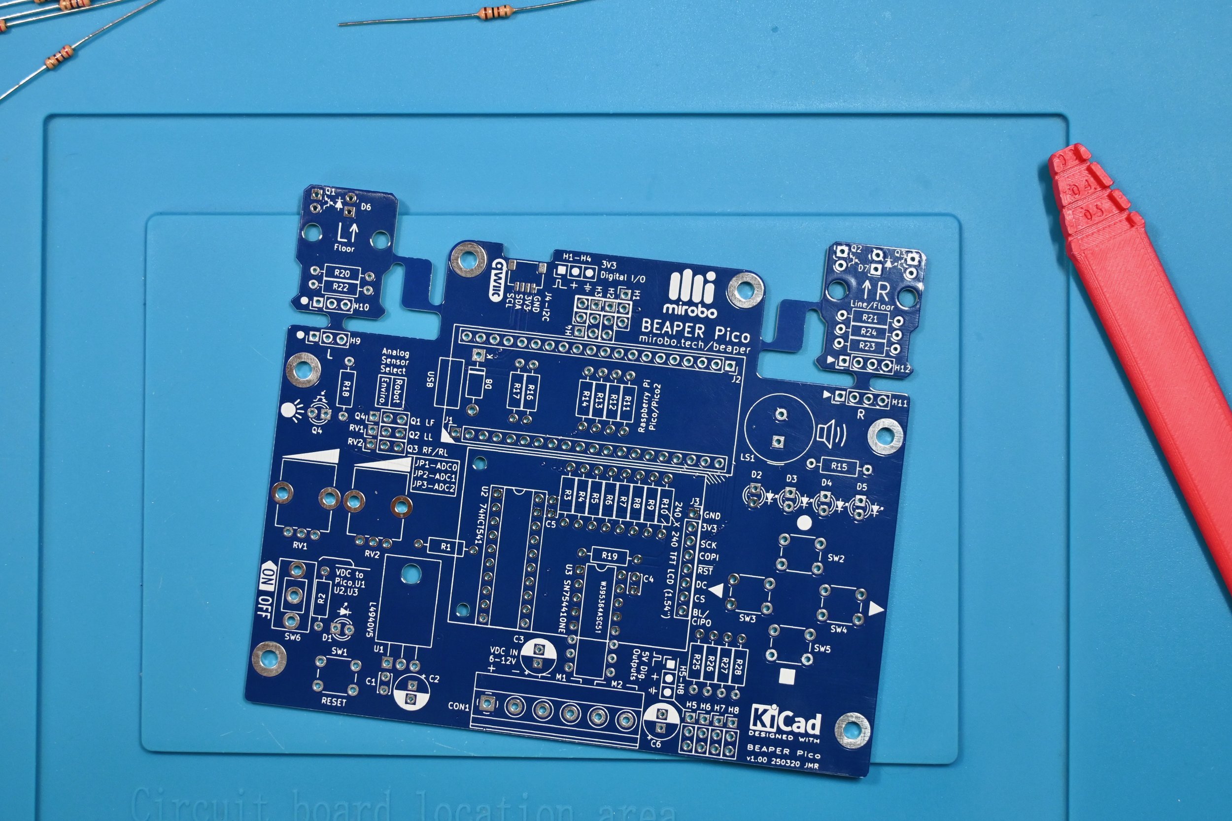
Gather all of the required tools and equipment before starting assembly of your BEAPER Pico. We recommend:
a soldering iron with a fine tip for soldering all of the through-hole parts, as well as an ultra-fine conical tip or flat blade tip for soldering the optional QWIIC connector’s surface mount (SMT) pins
electronic solder formulated with a no-clean, or water soluble flux
diagonal cutters or low-profile shear cutters to trim component leads after soldering
the BEAPER Pico schematic diagram for reference as well as to help you decide which components you will need to install for the configuration you plan to build

View or download the BEAPER Pico v1.00 schematic diagram (.PDF).
Step 1 – Select your configuration
BEAPER Pico is designed in a way that allows you to choose its final build configuration. All configurations include a common set of components, and these components are shown without dashed outlines on the schematic. Adding one or more groups of optional components (shown inside dashed outlines on the schematic) enables users to customize BEAPER Pico for specific applications, or to create custom build configurations.
The assembly instructions describe two common starter build configurations, as well as the full-build configuration. The starter configurations use fewer parts and allow users to start programming their BEAPER Pico circuit more quickly. They are the Educational Starter configuration, which contains just the components necessary for learning programming using the Introductory Learning Activities, and the Robot Starter configuration, which contains all of the components needed to build BEAPER Pico as a simple robot.
Optional sets of components can be added to either starter configuration at any time to enable additional features and capabilities, or to fully assemble the BEAPER Pico circuit. The colour-coded descriptions, below, show which options work well with each configuration and will also guide you through the assembly of each configuration.
Educational Starter
Build the Educational Starter configuration to start learning programming using the five Introductory Learning Activities on this site.
Optional components designed to provide more versatile capabilities for the Educational Starter configuration include one or more of the following:
an ambient light sensor
one or two analog potentiometers
a 1.54”, 240x240 pixel graphical LCD display
four 3.3V digital I/O expansion header pins or a socket that can also be shared by:
a 3.3V ultrasonic SONAR distance sensor module
Robot Starter
The Robot Starter configuration includes all of the components needed to complete the Introductory Learning Activities as well as components that add a voltage regulator, 5V level shifter and a motor driver circuits, and a header socket for a 3.3V ultrasonic SONAR distance sensing module.
Optional components that can provide additional capabilities for robots in this configuration include:
up to four 5V servo output headers
parts for the both optical floor and line sensor modules containing IR floor illumination LEDs, IR phototransistors, and optional extension cables and connectors
a QWIIC connector for interfacing with external I2C devices
Optional/IoT/Full Build
Optional components can be added to any configuration to enable additional features and capabilities, including creating an IoT-focused Build, or a Full Build enabling all of BEAPER Pico’s external interfaces.
Note that not all of the features and capabilities of BEAPER Pico can be used at the same time. See the BEAPER Pico schematic diagram for complete circuit details.
Optional components that can provide more diverse learning opportunities with BEAPER Pico include:
a QWIIC connector for connecting external I2C devices
a 1.54” 240x240pixel graphical LCD display
Step 2 - Check your components
All of the components needed to assemble BEAPER Pico, as well as a few optional components, are listed in this shared DigiKey BEAPER Pico parts list . This makes it easy to order the parts as well as check that you have all of the required components in your kit.
BEAPER Pico electronic parts kit components
The BEAPER Pico electronic parts kit comes with all of the electronic components that get assembled onto the BEAPER Pico circuit board, including the parts needed to fully populate both of the integrated optical robot floor/line sensor modules.
The BEAPER Pico electronic parts kit does not include: a Raspberry Pi Pico microcontroller, an LCD display, an ultrasonic SONAR distance sensing module, the motors, wheels, battery holder, or chassis used to make a robot, or the wiring necessary to reconnect the optical floor/line sensor modules after detachment. Some of these components are available as optional add-on kits.
Additional required BEAPER Pico components
To fully complete your BEAPER Pico circuit so that you can program it after assembling it, you will need:
a Raspberry Pi Pico, Pico W, Pico 2, or Pico 2 W microcontroller module with soldered header pins, and
a USB 2.0 micro (Type-B) cable to connect it to your computer
Optional BEAPER Pico add-ons
BEAPER Pico can be extended with a variety of additional parts, including:
a 3.3V HC-SR04P ultrasonic SONAR distance sensor module
a 1.54” 240x240 pixel SPI TFT LCD display
3.3V I2C devices, and Sparkfun QWIIC-compatible JST-SH extension cables to connect them
5V hobby servos
NeoPixel RGB LED strips
robot parts, including low-current, 6-12V DC gear motors, battery holders, and extension cables (commonly referred to as Dupont connectors) to reconnect broken-away optical sensor modules
Step 3 - Assemble your BEAPER Pico
Electronic components are often installed into circuit boards in order from the smallest physical height to the tallest in order to make manual assembly of circuit boards easier, and these assembly instructions follow this general pattern.
Optional components can be installed at any time, but assembling the components in the order shown in the steps below will make installation of some components easier. If you want to start with a simpler build configuration and expand your BEAPER Pico later, you may want to consider adding some of the extra components as you get to their installation steps to make installation easier.
The assembly steps are colour-coded showing the recommended parts for each configuration.
Components in the green assembly steps are installed as a part of all configurations.
Installing only the components listed in the green steps completes BEAPER Pico in the Educational Starter configuration using the minimum number of parts necessary to start learning programming using the introductory programming activities.
Components in the red assembly steps are additional parts which, when added to the parts listed in the green assembly steps, complete BEAPER Pico in the Robot Starter configuration.
Some of these components may not be necessary if you’re not building your BEAPER Pico into a robot. You’ll also need to choose between installing header pins or a header socket (for a SONAR module) in H1-H4 as part of this configuration.
Components listed in the blue assembly steps are optional and can be installed in addition to the parts installed in either starter configuration.
Installing all of the optional parts produces the full build configuration of BEAPER Pico.


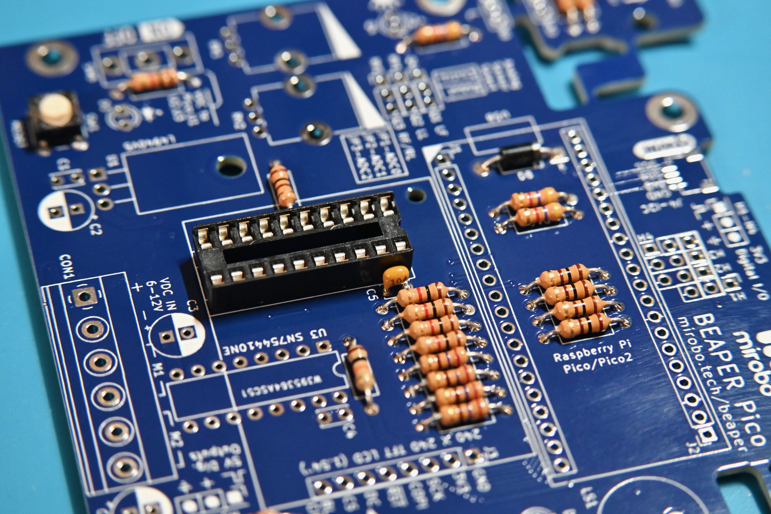
User I/O device resistors
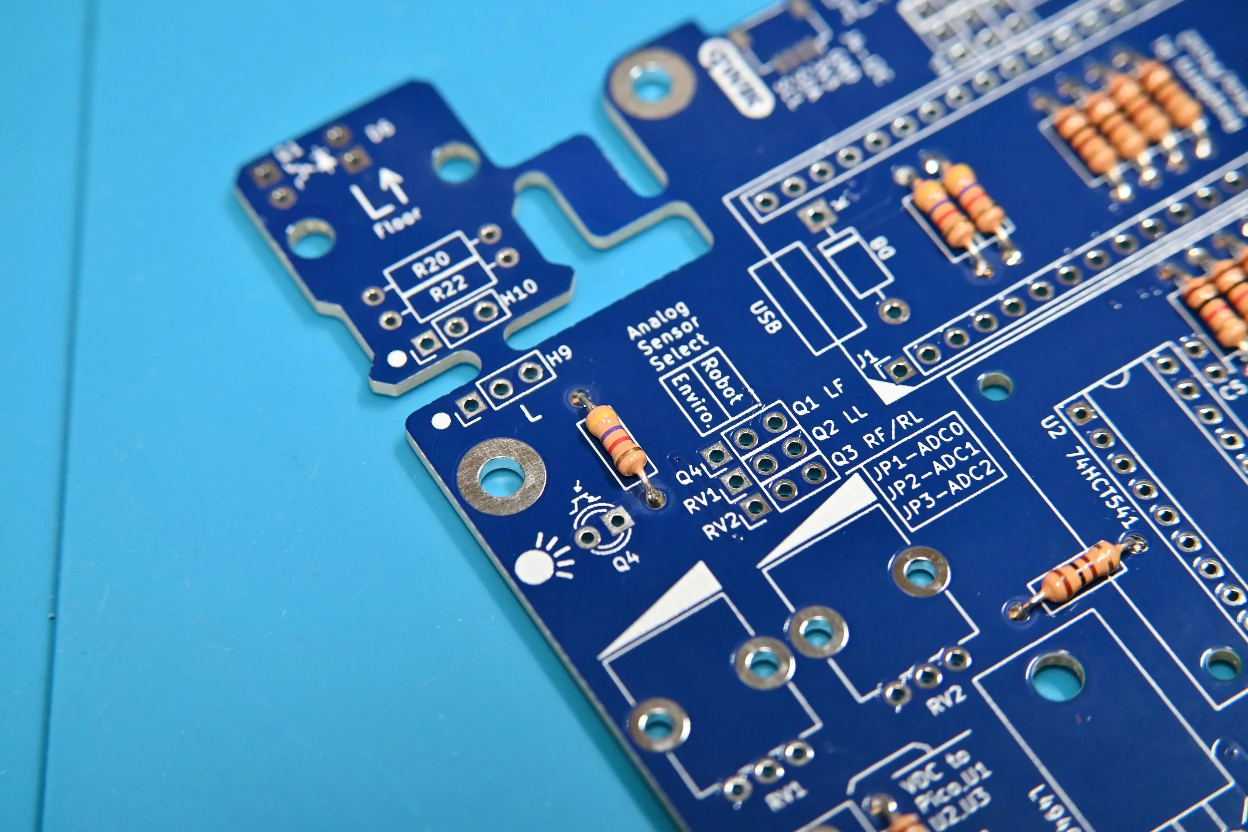
Resistor installation tip: pre-bend the resistor leads to make it easier to install the resistors in the PCB.
Install 100 Ω resistor R1 for the RESET pushbutton circuit.
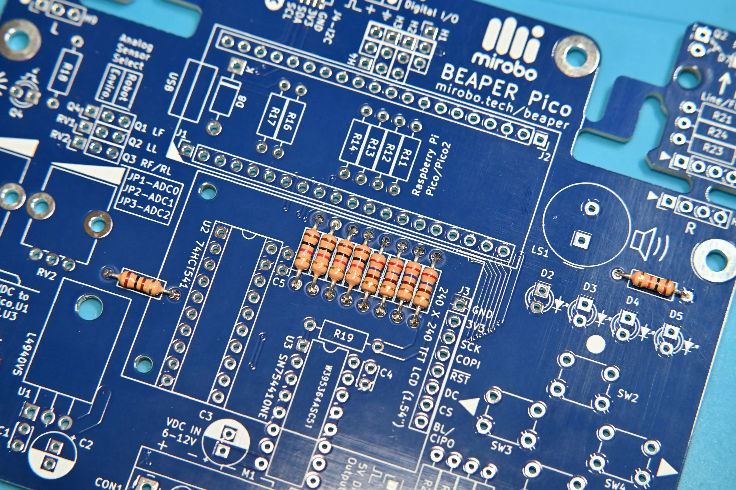
Install 1.0 kΩ pushbutton series current-limiting resistors R3, R4, R5, and R6.
Install 1.0 kΩ piezo load resistor R15.
Install 270 Ω LED series current-limiting resistors R7, R8, R9, and R10.
Battery voltage indicator LED resistor
Install 1.0 kΩ LED series current-limiting resistor R2 for battery voltage indicator LED D1.

3.3V digital I/O expansion header series resistors
Install 100 Ω series resistors R11, R12, R13, and R14 to connect the Raspberry Pi Pico to 3.3V expansion headers H1-H4.
A header socket for a 3.3V ultrasonic SONAR distance sensing module will be added in a later step for the Robot Starter configuration. Alternatively, header pins can be added instead of the header socket to make it easier to connect external 3.3V I/O devices.

Optional I2C/QWIIC pull-up resistors
Install 4.7 kΩ I2C bus pull-up resistors R16 and R17.
External I2C devices can be connected using a QWIIC-compatible JST-SH connector, and these two I2C signal pull-up resistors are usually required.

Optional light sensor pull-up resistor
Install 4.7 kΩ pull-up resistor R18 if ambient light sensor Q4 will be used.
Q4 and jumper header JP1 will be installed in a later step.
Motor driver output enable pull-up resistor
Install 10k Ω pull-up resistor R19. This pull-up resistor is used to enable the motor outputs on the motor driver IC.
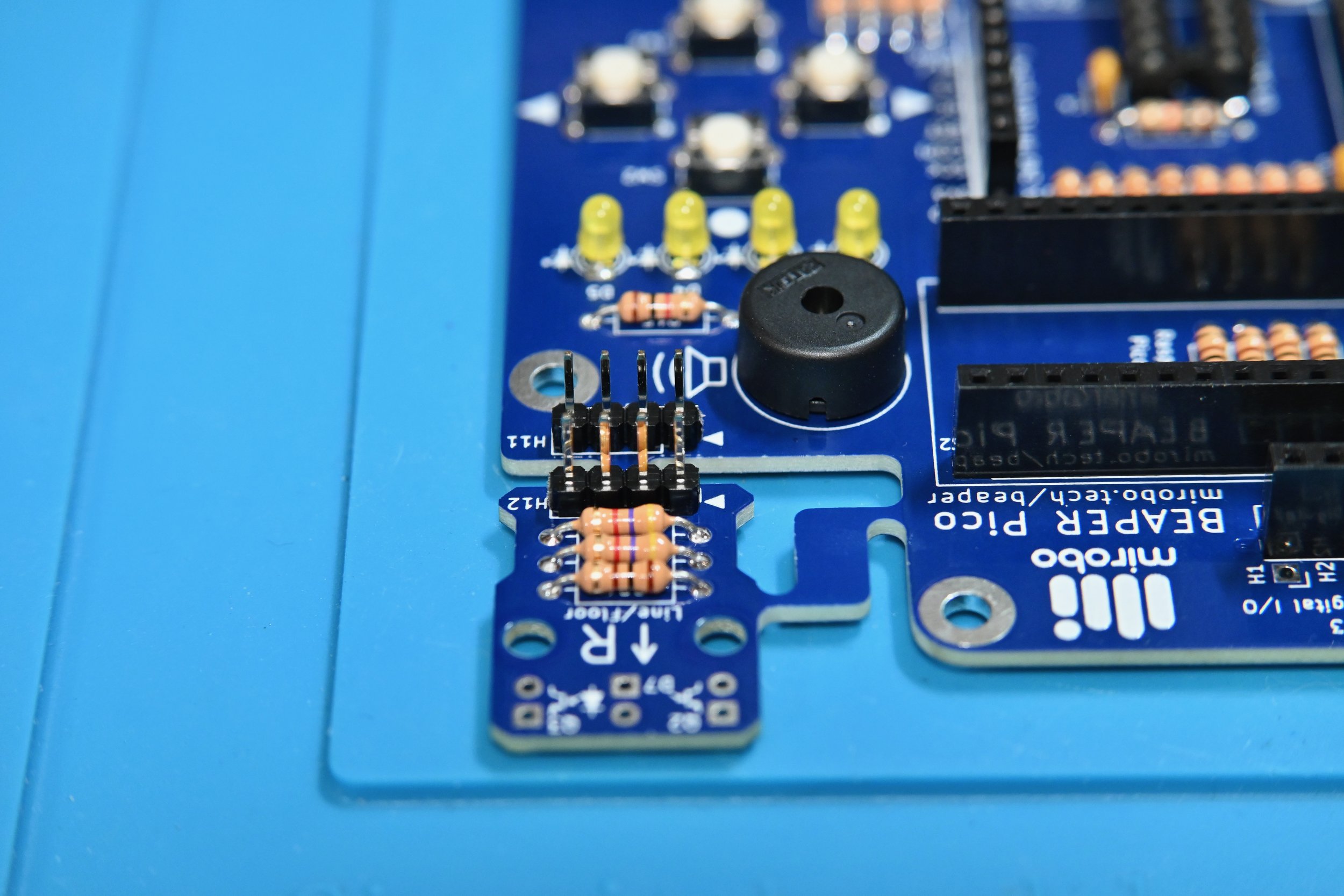
Optical floor sensor resistors
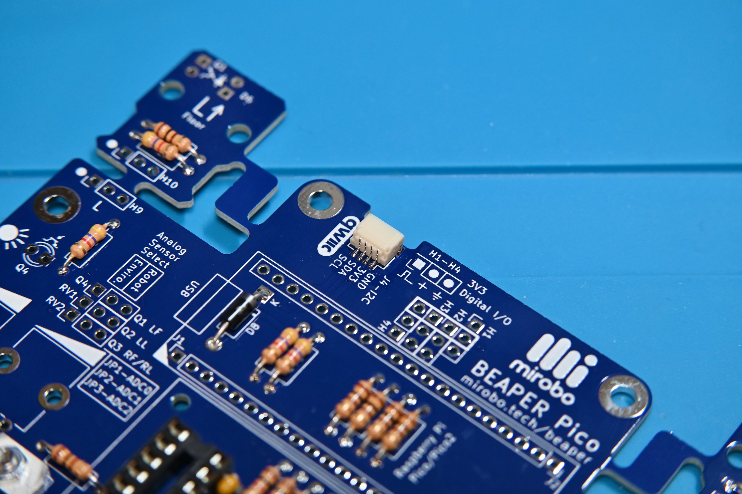
The BEAPER Pico PCB features integrated left (labelled L) and right (labelled R) optical sensor modules designed to make it easy to create robot floor or line sensors. These sensor modules can remain attached to the PCB to make floor sensors, or they can be detached from the main PCB to create robot line sensors or other types of optical sensors.
Install 100 Ω LED series current limiting resistors R20 and R21 to enable the use of optical floor illumination LEDs D6 and D7, respectively.
Install 4.7 kΩ phototransistor pull-up resistors R22, R23, and R24.

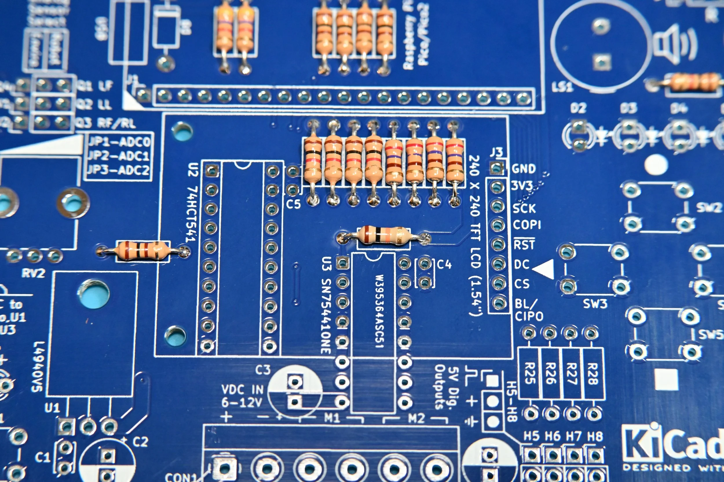
Optional 5V digital output resistors
Install 100 Ω series resistors R25, R26, R27, and R28 to connect the Raspberry Pi Pico to 5V digital output headers H5-H8.
Header pins can be installed in H5-H8 to enable BEAPER Pico to control 5V hobby servos or other 5V digital devices, and these will be installed in a later step.

Install the pushbuttons
Install RESET pushbutton SW1, and user pushbuttons SW2, SW3, SW4, and SW5.

Protection diode
Install the SB140 (or equivalent) Schottkey protection diode D8.
Match its cathode end with the painted stripe to the line on the diode symbol marked with the letter K on the silkscreen.

Level shifter IC circuit components
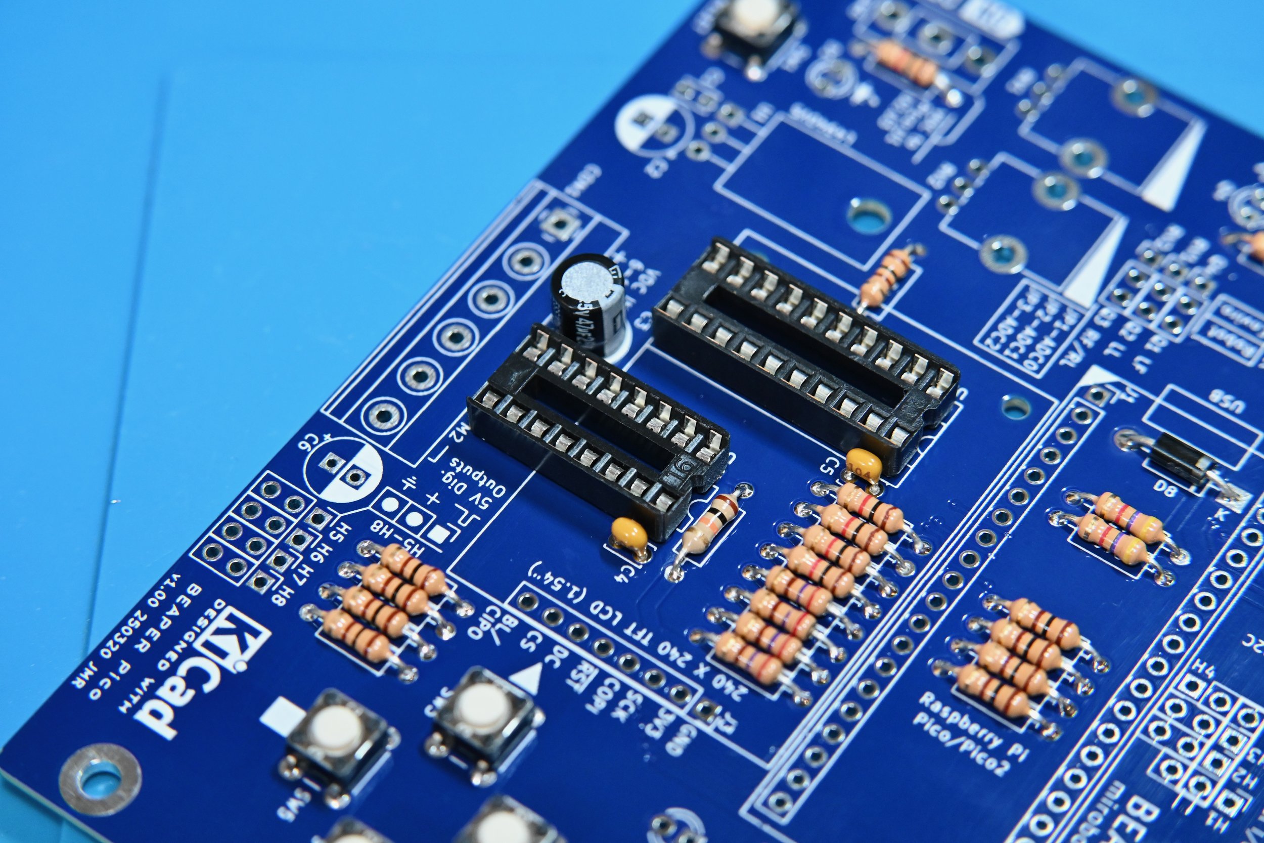
Install a 20-pin DIP IC socket for level shifter IC U2.
Match the pin 1 identification notch molded into one end of the IC socket to the painted notch on the PCB silkscreen (closest to the Raspberry Pi Pico socket).
Install 100 nF decoupling capacitor C5 beside the IC socket. The 100 nF capacitors are not polarized so their orientation does not matter.
Motor driver IC circuit components
A 16-pin DIP IC socket should be installed for motor driver IC U3 when BEAPER Pico is used in educational settings, or when the motor current will be kept low. Since the PCB ground plane acts as a heat sink, it is better to solder the motor driver IC directly into the PCB when using high current motors (although this makes replacement in the event of a motor driver IC failure much more difficult).
Install 100 nF decoupling capacitor C4 beside the IC socket.
Install 47 µF electrolytic filter capacitor C3 with its long lead into the square PCB pad. The location of the negative polarity stipe on the capacitor must match the filled half of the capacitor silkscreen outline on the PCB.
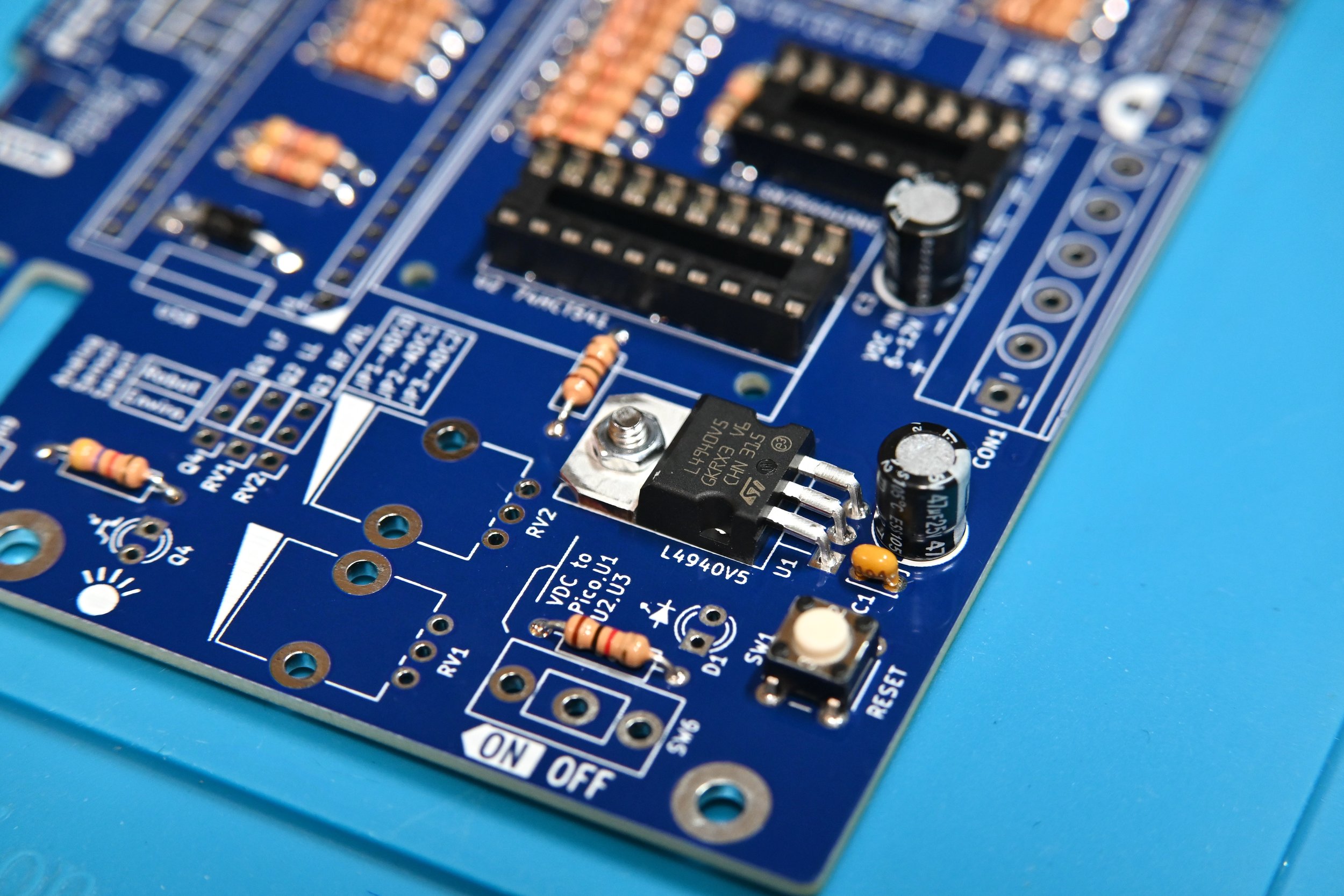
Voltage regulator circuit components
Install the L4940V5 low-dropout regulator U1. Bend its leads to fit the PCB spacing and secure the regulator using a #4-40 or M3 bolt inserted from the back side of the PCB. Fasten a nut on the top side of the regulator’s tab to secure the regulator to the PCB. This arrangement works best to ensure that a longer mounting bolt won’t protrude from the bottom of the PCB where it might interfere with mounting the PCB to a robot chassis.
Install 100 nF regulator input capacitor C1.
Install 47 µF electrolytic output filter capacitor C2. The long lead of the capacitor gets inserted into the square pad on the PCB, and the negative polarity stripe on the capacitor must match the filled half of the capacitor silkscreen outline on the PCB.
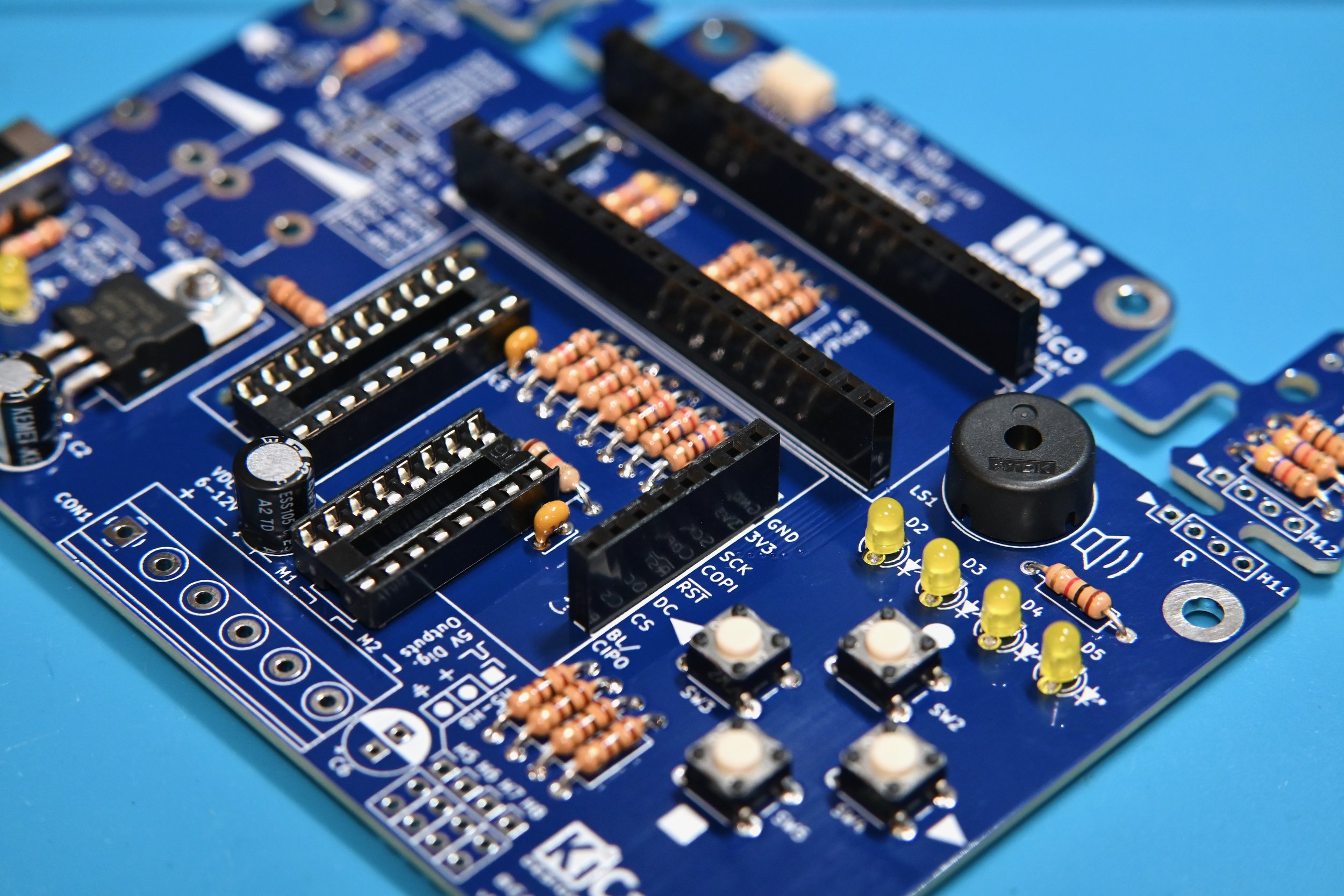
Install the piezo buzzer and user LEDs
Install piezo buzzer LS1.
Kits are normally supplied with a non-polarized buzzer so its orientation in the PCB does not matter. If a polarized buzzer is used instead, install the positive terminal into the marked pad closest to the silkscreen legend LS1.
Install user LEDs D2, D3, D4, and D5. All LEDS must be installed with their long leads inserted into the square PCB pads and their short leads into the round pads.
This is opposite to common PCB practice but was done for simplicity and commonality with other components having different length leads (electrolytic capacitors, ambient light sensor, and phototransistor), which helps to reduce problems for new learners in a classroom setting. Small schematic silkscreen symbols beside the LEDs and phototransistors show the proper LED polarity.

Install the power switch and LED indicator
Install power switch SW6.
It connects an external battery attached to the screw terminal strip (CON1) to the voltage regulator, the 5V IC circuits, and allows the battery to power the microcontroller.
Install power indicator LED D1 with its long lead in the square PCB pad closest to the D1 legend on the silkscreen.

Optional I2C QWIIC connector
Installing the QWIIC-style I2C connector at this time is recommended if you think it might be used at any future point. Its solder terminals will be easier to access now than after the Raspberry Pi Pico header sockets have been installed!
Use an ultra-fine point soldering iron to solder all four bus pins as well as the two mounting tabs of JST-SH connector J4, the Sparkfun QWIIC-compatible I2C connector.
Alternatively, the connector can be soldered using solder paste and a hot plate, or by using liquid solder flux and dragging the solder using a flat/blade soldering iron tip.
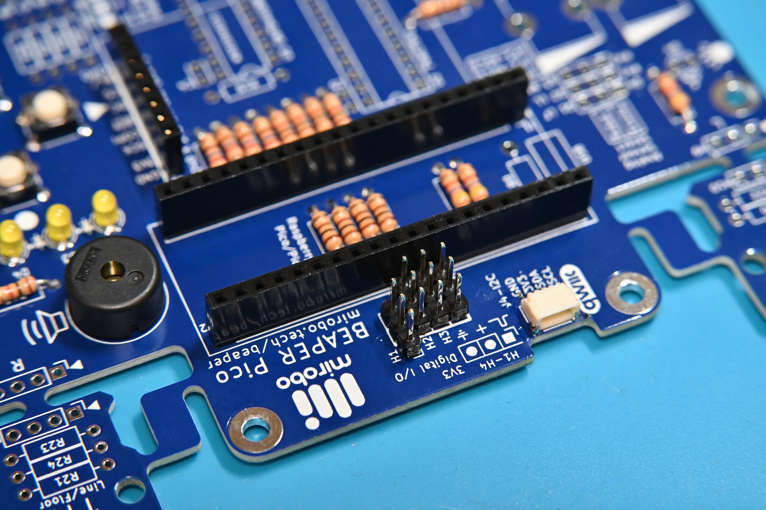
Raspberry Pi Pico header sockets
Install the two 20-pin headers sockets, J1 and J2. These will be used to mount the Raspberry Pi Pico microcontroller in BEAPER Pico, and it will be easier to solder them in straight by mounting them on a Raspberry Pi Pico circuit board before soldering.
At this point, the Educational Starter configuration is complete! Inspect the soldering, and check and fix any poor solder connections or short circuits. Clean the circuit board board with a flux remover recommended for the type of solder that was used, and allow the PCB to fully dry before inserting your Raspberry Pi Pico into its sockets as shown in the last assembly step.

Optional LCD/SPI header socket
Install 8-pin header socket J3 for the optional 1.54” TFT LCD display.
Alternatively, header pins (not included in the kit) may be substituted for the socket to break out the pins of the Raspberry Pi Pico’s SPI bus so these can be used to connect to external devices.
Distance sensor module header socket
If you plan on using a 3.3V ultrasonic SONAR distance sensor module with your BEAPER Pico robot, install a 4-pin header socket in BEAPER Pico now. The socket bridges across the four H1-H4 headers, as indicated by the slightly thicker rectangular outline on the PCB.
Alternatively, header pins can be installed in each of the H1-H4 header positions as shown in the next step.

Optional 3.3V I/O header pins
Install 3-pin analog/digital I/O headers into one or more of the H1-H4 headers to make it easier to connect external I/O devices if you don’t plan to mount the ultrasonic SONAR distance sensor module onto the PCB.
If the socket for a SONAR distance sensor module is installed, header pins can still be installed beside the header socket for convenient access to +3.3V, ground, and the unused signal pins on H1 and H4.
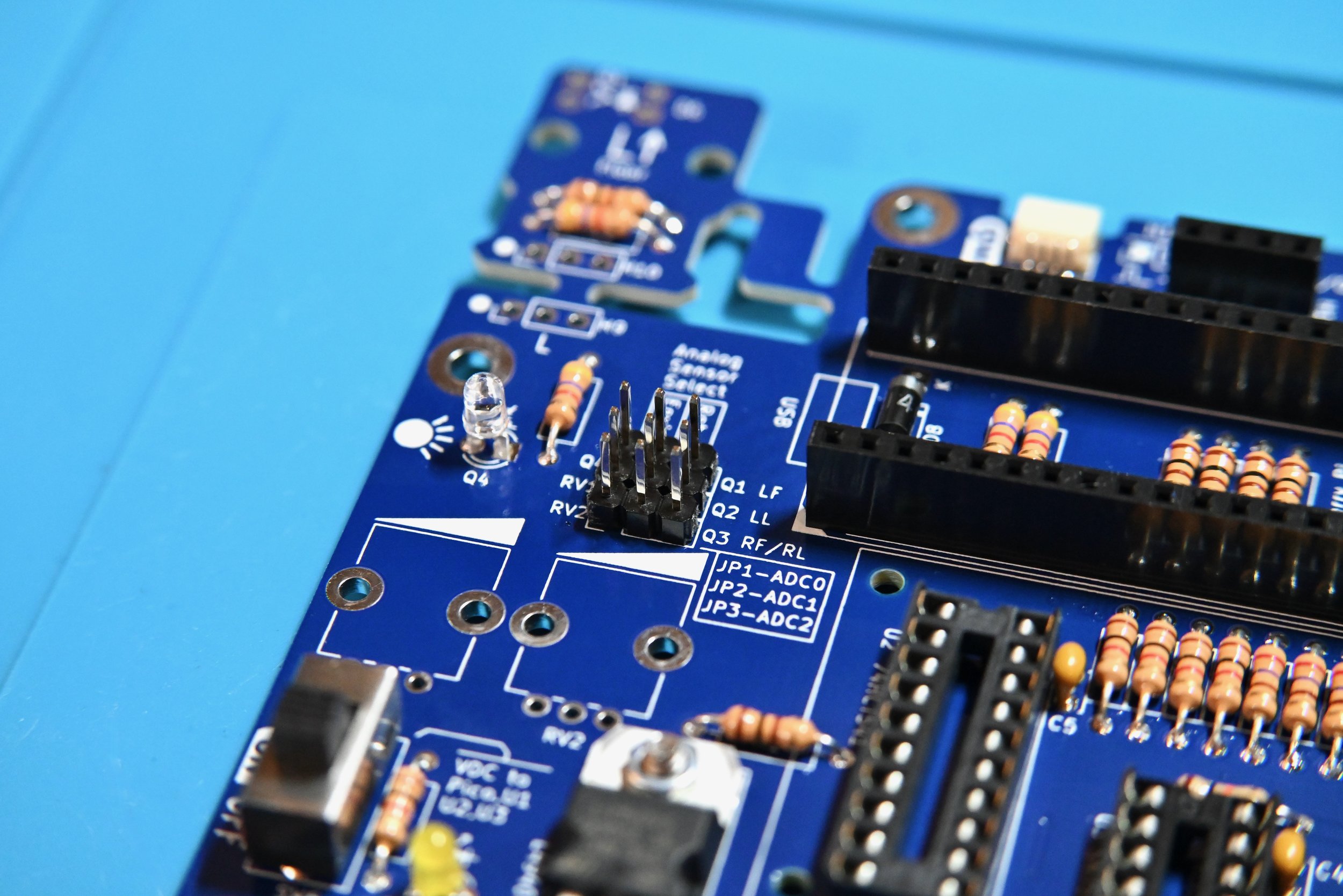
Optional ambient light sensor
Install ambient light sensor Q4 with its long (emitter) lead in the square pad. If using a different type of light sensor, match its collector and emitter pins with the phototransistor image shown on the silkscreen.
Jumper JP1 must be installed (in the next step) to allow the Raspberry Pi Pico to connect to the ambient light sensor.

Install the analog sensor select headers
Install 3-pin jumper headers JP1, JP2, and JP3. They are required to connect the robot phototransistors Q1, Q2, and Q3 to the analog input pins of the Raspberry Pico microcontroller module.
Shorting jumpers connecting across two pins of each jumper header route the analog signals from either the robot-focused analog input devices, or the optional ambient light sensor, optional analog temperature sensor, and optional rotary potentiometers – collectively referred to and labeled as environmental (Enviro.) sensors – to the Raspberry Pi Pico ADC input pins.
Optional 5V digital output headers
Install 3-pin digital output headers H5, H6, H7, and H8 to connect external digital output devices.
Install 47 µF capacitor C6 if the headers will be used with hobby servo motors or other high current output devices.

Optional optical floor sensor headers
The LEDs and phototransistors in the L (left) and R (right) optical sensor modules are electrically connected to the main BEAPER Pico board while the modules remain physically attached. If the modules are snapped off, they can be electrically connected by attaching jumper wires between 3-pin headers H9 and H10, and 4-pin headers H11 and H12.
Install 3-pin headers H9 and H10 to allow for re-connection of the L floor sensor module.
Instal 4-pin headers H11 and H12 to allow for re-connection of the R line/floor sensor module.

Install the screw terminal strip
Install screw terminal strip CON1, ensuring its wire entry openings face the outside edge of the PCB.
At this point, the Robot Starter configuration main PCB assembly is complete! Inspect the soldering and check and fix any poor solder connections or short circuits. Then, clean the circuit board board with a flux remover recommended for the type of solder flux used, and allow the PCB to fully dry before installing the ICs, jumper shunts, and your Raspberry Pi Pico.
If optical floor or line sensors will be used as part of your robot build, it is recommended that you install them after the BEAPER Pico PCB or its detached optical sensor modules, have been installed into your assembled robot chassis. This allows the phototransistors and LEDs to be positioned at the proper distance from the floor for maximum sensitivity and effectiveness.

Optional analog potentiometers
Install one or both of the 10 kΩ potentiometers into RV1 and RV2. Solder the three signal pins as well as the two retaining pins attached to the metal shell of each potentiometer.
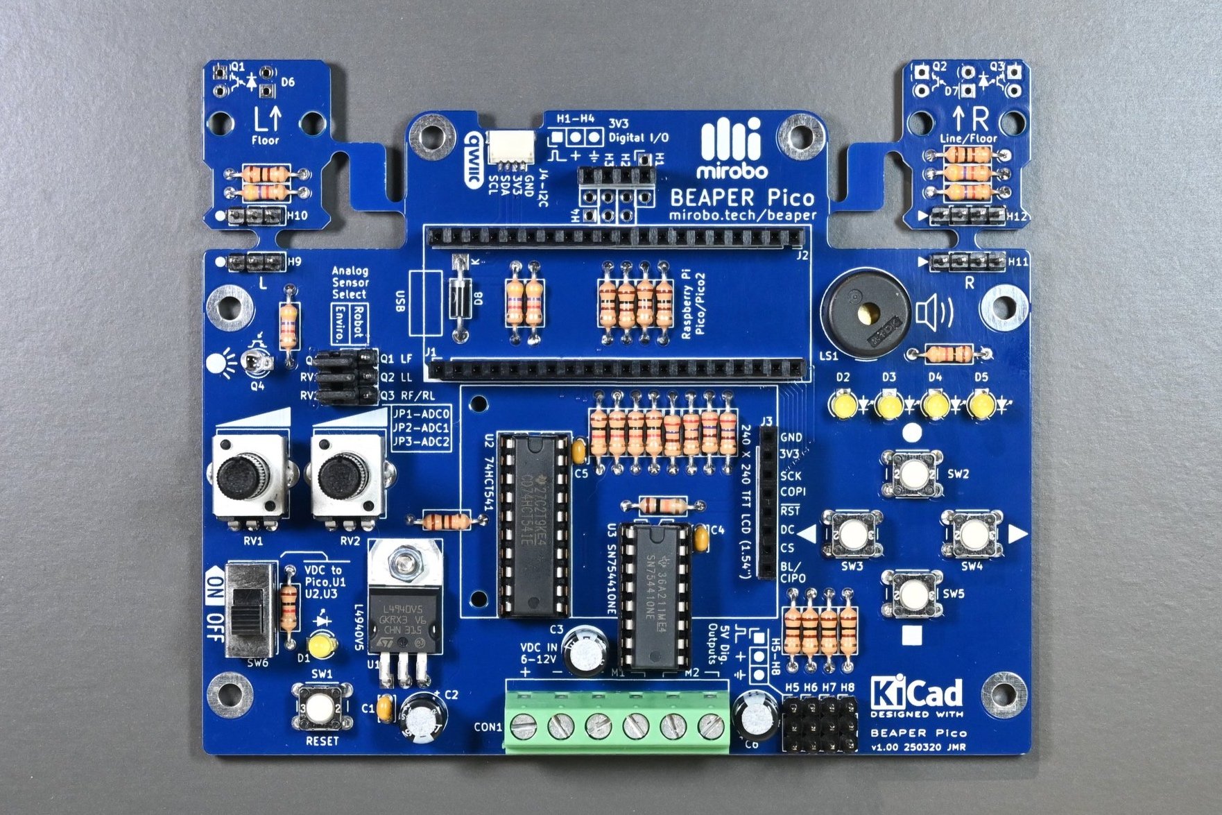
At this point, the full build is complete! Inspect the soldering and check and fix any poor solder connections or short circuits. Then, clean the circuit board board with a flux remover recommended for the type of solder flux used, and allow the PCB to fully dry before installing the ICs, jumper shunts, and your Raspberry Pi Pico.

Prepare the ICs for installation
Prepare the octal buffer/level shifter and motor driver ICs for installation into their sockets (or just the buffer if you’ve already soldered the motor driver IC into the circuit board in a prior step). Straighten the pins of each IC so that they face directly downward and are perpendicular to the body of the IC as shown by the left IC in the photo.
This is easy to do by laying each row of the IC’s pins flat against a table and applying downward pressure while carefully rotating the IC’s body into a vertical position.

Install the ICs
Insert each IC into its socket, carefully aligning its leads between the dual metal contacts of each row of the IC socket. Be sure to match each IC’s molded notch (or pin 1 dot) to the matching notch in each IC socket. When all of the pins are aligned in their sockets, gently press each IC firmly into place.

Analog Sensor Select jumper shunts
BEAPER Pico’s analog inputs are shared by pairs of analog devices. Shorting jumper shunts are used to select which device of each pair is currently wired to each of the Raspberry Pi Pico’s three external analog input pins. The example photo shows all on-board analog environmental sensors (labelled Enviro.) being connected to the analog inputs of the Raspberry Pi Pico.

Install your Raspberry Pi Pico
Insert the header pins of your Raspberry Pi Pico microcontroller module (not supplied with the kit) into header sockets J1 and J2 such that the Raspberry Pi Pico’s USB connector faces the left side of BEAPER Pico (towards the analog sensor select jumpers).
If your Raspberry Pi Pico module does not have the headers soldered in, it’s easy to do this by inserting the long sides of both headers fully into the header sockets, placing the Raspberry Pi Pico module on top, and then carefully soldering all of its pins.

Optional LCD display
Hold the BEAPER LCD support (available to download from Makerworld if you’re supplying your own LCD) flat against the bottom side of the LCD panel (opposite the header pins), and insert M2 machine screws through each of the two LCD mounting holes opposite the header into the holes in the LCD support.
Align the protruding ends of the two M2 machine screws with the mounting holes in the BEAPER PCB, and press the LCD header pins into the J3 SPI header socket.
Fasten one M2 nut onto each of the two M2 machine screws on the underside of the BEAPER Pico PCB.

Raspberry Pi is a trademark of Raspberry Pi Ltd.