
Assembling ARPS-2
Get ready to assemble ARPS-2
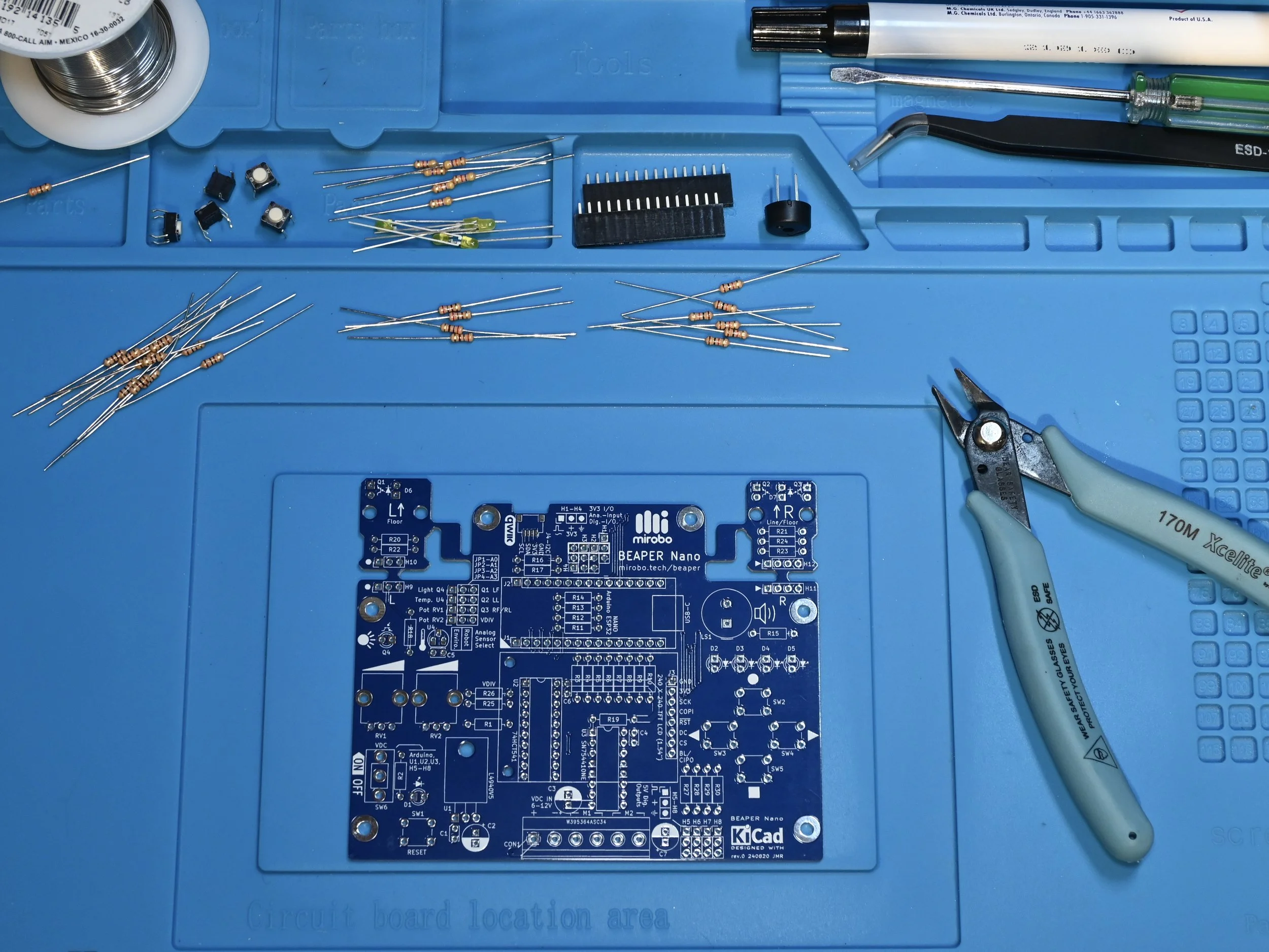
Gather all of the required tools and equipment before starting assembly of your ARPS or ARPS-2 circuit. While these steps specifically show the assembly of the newer ARPS-2, they can also be used to assemble the original ARPS circuit since they share the same parts.

View or download the ARPS-2 schematic diagram (PDF).
Required Resources
ARPS or ARPS-2 PCB (printed circuit board) and the required components for your configuration
fine-tip electronic soldering iron suitable for soldering through-hole electronic components
electronic solder formulated with no-clean or water soluble flux
low profile shear cutters (or small diagonal cutters) to trim component leads after soldering
Step 1 – Select your configuration
ARPS-2 is designed in a way that allows you to choose its final build configuration. All configurations include a common set of components – these are shown without dashed outlines on the schematic diagram. Installing only this small set of common components builds ARPS-2 in the Educational Starter configuration, which is the least expensive and quickest configuration to build and includes all of the components required to start using ARPS-2 to learn microcontroller programming with our introductory programming activities.
Optional components, shown inside dashed outlines on the schematic, enable users to customize ARPS-2 for specific applications, or to create custom build configurations. ARPS-2 is designed to make it easy to build robots, and the assembly instructions include a Robot Starter configuration which consists of the basic components required to create a simple robot.
Groups of optional parts add additional circuits and capabilities to your ARPS-2. An ARPS-2 with all or most of the optional parts added is considered to be the Full Build configuration. Optional sets of components can be added to either starter configuration at any time to enable additional features and capabilities, or to fully assemble your ARPS-2 circuit. The descriptions, below, list options which work well with each configuration, or special instructions for specific configurations:
Educational Starter
Build the ARPS-2 Educational Starter configuration and start learning Arduino programming quickly using the ARPS-2 Introductory Learning Activities.
Optional components recommended for the Educational Starter configuration:
an analog temperature sensor, or one or more of the optical floor sensor phototransistor circuits, or the battery voltage divider resistors are recommended in order to complete the fifth Introductory Learning Activity
Robot and I/O expansion components can easily be installed later.
Robot Starter
Start with the Robot Starter configuration when you know that your ARPS-2 will be built into a robot.
Special instructions for completing the Robot Starter configuration:
headers H1-H4 can be populated with either a 4-pin socket to mount a SONAR module on-board, or with header pins to make it easier to connect to the expansion header PCB
optical floor sensor LEDs and phototransistors must be installed at the proper height in a robot for best sensitivity – install these components only after the break-away optical floor sensor modules have been assembled into the robot
Optional/Full Build
Optional components can be installed at any time to add extra features and capabilities to your ARPS-2, or to customize it for your needs.
Special instructions for the full build:
headers H1-H4 can be populated with either header pins or a 4-pin socket (header pins may make it easier to connect external circuit modules, while the header socket is designed to mount a SONAR module on-board), or a mix of both – determine which is best for your application
Step 2 - Check your components
The ARPS-2 kit comes with all of the components that need to be soldered onto the ARPS-2 PCB, including components for the optional optical floor and line sensor modules. Use the parts lists, below, to confirm that all of the components have come with your kit.
If you have obtained bare ARPS or ARPS-2 printed circuit boards, the following DigiKey parts lists helpfully link to all of the necessary parts required to complete your circuit:
Additional ARPS-2 components
The ARPS-2 kit does not include an Arduino® UNO microcontroller, an ultrasonic SONAR distance sensing module, or any of the components required to make a robot such as the extension wires needed to reconnect the optical floor/line sensor modules after detachment.
To start programming your ARPS-2 you will need an Arduino UNO R4 Minima microcontroller (recommended as the most cost-effective option), or an Arduino UNO R4 WiFi, or an Arduino UNO R3, and the appropriate USB 2.0 cable necessary to connect the Arduino to your computer.
Optional ARPS-2 add-ons
ARPS-2 supports a variety of external devices, including:
one 5V HC-SR04 ultrasonic SONAR distance sensor module
two low-current (under 500mA), 6-12V DC gear motors (with bi-directional control), or up to four DC motors (single direction only), or one bi-polar stepper motor
up to six 5V hobby servos or other 3-pin digital I/O devices
up to two 3-pin analog input devices
an external 6-12V battery or battery holder
two break-away optical sensor modules (part of the ARPS-2 circuit) that can be connected to ARPS-2 using 0.1” socket extension cables (sometimes called DuPont connectors/cables)
Step 3 - Assemble your ARPS-2
Electronic components are often installed into circuit boards in order from the smallest to the tallest in physical size to make manual assembly of circuit boards easier. The assembly steps, below, mostly stick with this convention.
Each set of optional components can be installed at any time, but assembling all of the components in the order of the assembly steps may make the installation of some components easier.
The assembly steps are colour-coded for the three most common configurations: green, for the educational starter configuration, red for the robot starter configuration, and blue for all optional groups of components. Follow the colour-coded steps to install the recommended parts for your chosen configuration.
Components listed in the green assembly steps are installed for all configurations.
The educational starter configuration can be completed using only the components in the green assembly steps.

Components listed in the red assembly steps build the robot starter configuration when added to the components in the green steps.

Components listed in the blue assembly steps are optional and can be installed at any time to add new features and capabilities to ARPS-2. Use the schematic diagram to determine which features should be installed for your build.

User I/O device resistors
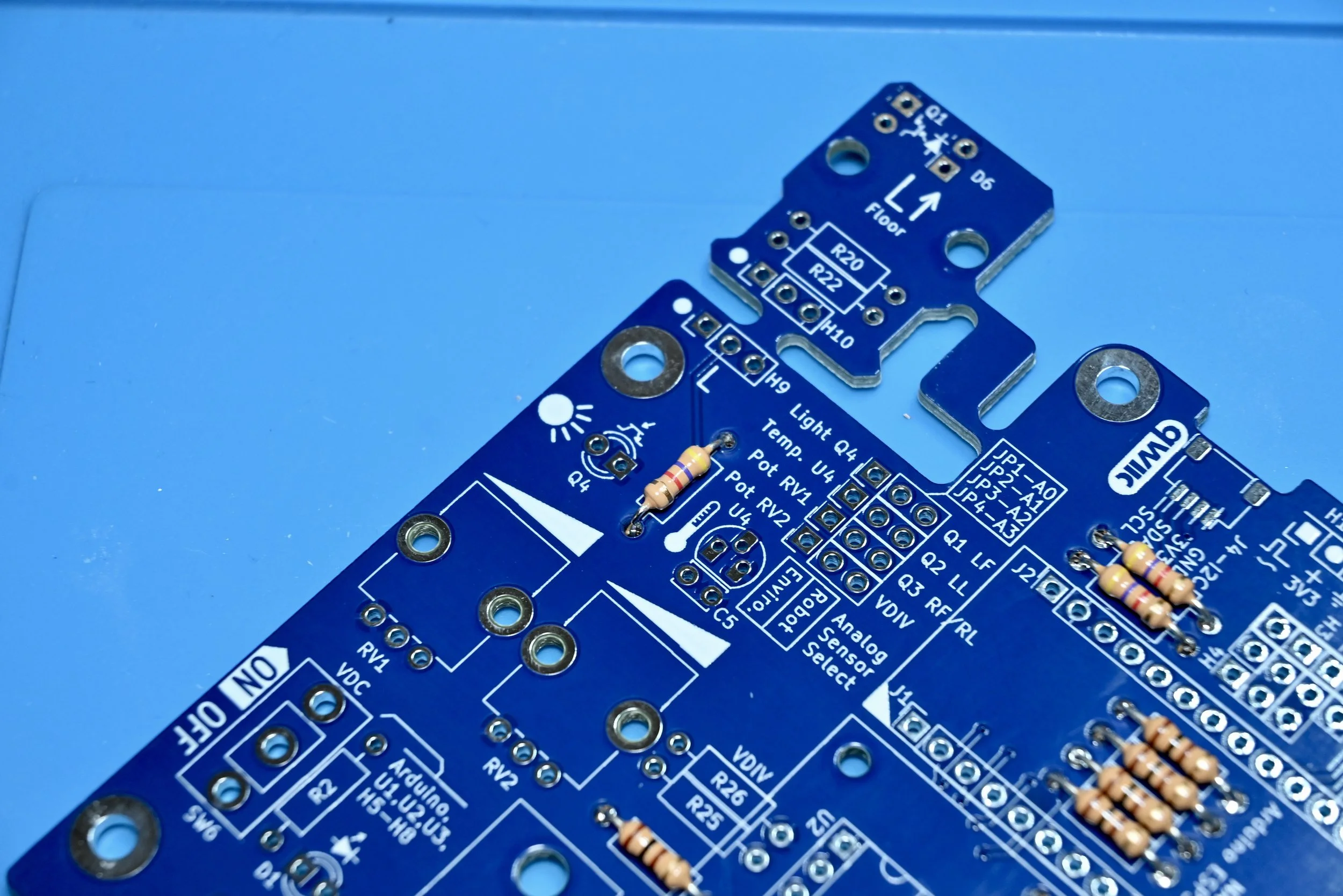
Resistor installation tip: pre-bend the resistor leads to make it easier to install the resistors in the PCB.
Install 100 Ω resistor R1 for the RESET pushbutton circuit.
Install 1.0 kΩ pushbutton series current-limiting resistors R3, R4, R5, and R6.
Install 1.0 kΩ piezo load resistor R15.
Install 270 Ω LED series current-limiting resistors R7, R8, R9, and R10.

Battery voltage indicator LED resistor
Install 1.0 kΩ LED series current-limiting resistor R2 for VDC (battery voltage) indicator LED D1.

3.3V analog input/digital I/O expansion header series resistors
Install 100 Ω series resistors R11, R12, R13, and R14 to connect the Arduino Nano ESP32 to 3.3V expansion headers H1-H4.
A header socket for a 3.3V ultrasonic SONAR distance sensing module will be added in a later step for the Robot Starter configuration. Alternatively, header pins can be added instead of the header socket to make it easier to connect external 3.3V I/O devices.

Optional I2C/QWIIC pull-up resistors
Install 4.7 kΩ I2C bus pull-up resistors R16 and R17.
I2C communication is possible using either header pins H1 and H4, or using JST-SH QWIIC connector J4, and 4.7k I2C pull-up resistors are usually required on both the SDA and SCL signal pins.

Optional light sensor pull-up resistor
Install 4.7 kΩ pull-up resistor R18 if the ambient light sensor, Q4, will be used.
Q4 and jumper header JP1 will be installed in a later step.
Motor driver pull-up resistor
Install 10 kΩ pull-up resistor R19. This pull-up resistor enables the motor outputs on the motor driver IC.

Optional optical floor sensor resistors
The BEAPER Nano PCB features integrated left (labelled L) and right (labelled R) optical sensor modules designed to make it easy to create robot floor or line sensors. These sensor modules can remain attached to the PCB to make floor sensors, or the modules can be detached from the main PCB to create robot line sensors or other types of optical sensors.
Install 100 Ω LED series current limiting resistors R20 and R21 to enable the use of optical floor illumination LEDs D6 and D7, respectively.
Install 4.7 kΩ phototransistor pull-up resistors R22, R23, and R24.

Optional voltage divider resistors
These resistors form a voltage divider to reduce the battery potential to less than 3.3V allowing the Arduino Nano ESP32 to safely sense the battery potential.
Install 5.1 kΩ 1% resistor R25.
Install 976 Ω 1% resistor R26.

Optional 5V digital output resistors
Install 100 Ω series resistors R27, R28, R29, and R30 to connect the Arduino Nano ESP32 to 5V digital output headers H5-H8.
Header pins can be installed in H5-H8 to enable BEAPER Nano to control 5V hobby servos or other 5V digital devices, and these will be installed in a later step.

Install the pushbuttons
Install RESET pushbutton SW1, and user pushbuttons SW2, SW3, SW4, and SW5.
Installation tip: many pushbuttons have short leads, but trimming them after soldering will make the PCB easier to handle.

Level shifter IC circuit components
Install a 20-pin DIP IC socket for level shifter IC U2.
Match the pin 1 identification notch molded into one end of the IC socket to the painted notch on the PCB silkscreen.
Install 100 nF decoupling capacitor C6 beside the IC socket. The 100 nF capacitors are not polarized so its orientation does not matter.

Motor driver IC circuit components
A 16-pin DIP IC socket should be installed for motor driver IC U3 when BEAPER Nano is used in educational settings, or when the motor current can be kept low. Since the PCB ground plane acts as a heat sink, it is better to solder the motor driver IC directly into the PCB when using high current motors (although this makes replacement in the event of a motor driver IC failure much more difficult).
Install 100 nF decoupling capacitor C4 beside the IC socket.
Install 47 µF electrolytic filter capacitor C3 with its long lead into the square PCB pad. The location of the negative polarity stipe on the capacitor must match the filled silkscreen capacitor outline on the PCB.

Voltage regulator circuit components
Install the L4940V5 low-dropout regulator U1. Bend its leads to fit the PCB spacing and secure the regulator using a #4-40 or M3 bolt inserted from the back side of the PCB. Fasten a nut on the top side of the regulator’s tab to secure the regulator to the PCB. This arrangement works best to ensure that a longer mounting bolt won’t protrude from the bottom of the PCB where it might interfere with mounting the PCB to a robot chassis.
Install 100 nF regulator input capacitor C1.
Install 47 µF electrolytic output filter capacitor C2. The long lead of the capacitor gets inserted into the square pad on the PCB, and the negative polarity stripe on the capacitor must match the filled silkscreen outline on the PCB.

Install the piezo buzzer and user LEDs
Install piezo buzzer LS1.
Kits are normally supplied with a non-polarized buzzer so its orientation in the PCB does not matter. If a polarized buzzer is used instead, install the positive terminal into the marked pad closest to the silkscreen legend LS1.
Install user LEDs D2, D3, D4, and D5. All LEDS must be installed with their long leads inserted into the square PCB pads (closest to their D# part legends), and their short leads inserted into the round PCB pads.
This is opposite to common PCB practice but was done for simplicity and commonality with other components having different length leads (electrolytic capacitors, ambient light sensor, and phototransistor), which helps to reduce problems for new learners in a classroom setting. Small schematic silkscreen symbols beside the LEDs and phototransistors also show the proper polarity.

Install the power switch and LED indicator
Install power switch SW6.
It connects the external battery attached to the CON1 screw terminal strip to the voltage regulator, 5V logic and motor driver circuits, and the microcontroller.
Install power indicator LED D1 with its long lead in the square PCB pad closest to the D1 legend on the silkscreen.

Optional I2C QWIIC connector
Installing the QWIIC-style I2C connector at this time is recommended if you think it might be used at any future point. Installing it now makes it easier to access its solder terminals than after the installation of the Arduino Nano ESP32 header sockets.
Use an ultra-fine point soldering iron to solder all four bus pins as well as the two mounting tabs of JST-SH connector J4, the Sparkfun QWIIC-compatible I2C connector.
Alternatively, the connector can be soldered using solder paste and a hot air soldering system, or by using liquid solder flux and dragging the solder using a flat/blade soldering iron tip.

Arduino Nano ESP32 header sockets
Install the two 15-pin headers sockets, J1 and J2, used to mount the Arduino Nano ESP32.
At this point, the Educational Starter configuration is complete! Inspect the soldering and fix any poor solder connections or short circuits. Clean the circuit board board with a flux remover recommended for the type of solder that was used during assembly, and allow the PCB to fully dry before inserting the Arduino Nano ESP32 into its socket as shown in the very last assembly step.

Optional LCD/SPI header socket
Install 8-pin header socket J3 for the optional 1.54” TFT LCD display.
Alternatively, header pins (not included in the kit) may be substituted for the socket if this is a more convenient way to break out the Arduino Nano ESP32 SPI bus pins.

Distance sensor module header socket
Install a 4-pin header socket if the 3.3V ultrasonic SONAR distance sensor module will be mounted directly onto the BEAPER Nano PCB. The socket bridges across headers H1-H4, in the spot indicated by the slightly thicker rectangular outline on the PCB.
Alternatively, header pins for each of the H1-H4 headers can be installed as shown in the next step.

Optional 3.3V I/O header pins
Install 3-pin analog/digital I/O headers into one or more of the H1-H4 headers if the ultrasonic SONAR distance sensor module will not mounted into the PCB.
When the header socket for the distance sensor module is installed (as shown in the previous step), signal pins on headers H1 and H4 are still accessible and can be accessed by installing individual header pins, or pairs of header pins, in the spaces beside the header socket.

Optional ambient light sensor
Install ambient light sensor Q4 with its long (emitter) lead in the square pad. If using a different type of light sensor, match its collector and emitter pins with the phototransistor image on the silkscreen.
Jumper JP1 must be installed in a later step to allow the Arduino Nano ESP32 to connect to the ambient light sensor.

Optional temperature sensor
Install temperature sensor U4, matching its orientation to the silkscreen image.
Install 100 nF filter capacitor C5.
Jumper JP2 must be installed in a later step to enable the Arduino Nano ESP32 to connect to the temperature sensor.

Install the analog sensor select headers
Install 3-pin jumper headers JP1, JP2, JP3, and JP4. These jumpers are required to connect the robot phototransistors Q1, Q2, Q3, and the output of the battery voltage divider circuit to the analog inputs of the Arduino Nano ESP32 microcontroller module.
Shorting jumpers connecting across two pins of each jumper header allow for the selection of either the robot-focused analog input devices, or the optional ambient light sensor, optional analog temperature sensor, and optional rotary potentiometers, collectively referred to and labeled as environment (Enviro.) sensors.

Optional 5V digital output headers
Install 3-pin digital output headers H5, H6, H7, and H8 to connect external digital devices.
Install 47 µF capacitor C7 if the headers will be used with hobby servo motors to help filter their large motor currents.

Optional optical floor sensor headers
The LEDs and phototransistors in the L (left) and R (right) optical sensor modules are electrically connected to the main BEAPER Nano board while the modules remain physically attached. If the sensor modules are snapped off, jumper wires between 3-pin headers H9 and H10, and 4-pin headers H11 and H12, can be used to electrically reconnect the sensor modules with the main BEAPER Nano PCB.
Install 3-pin headers H9 and H10 to allow for re-connection of the L floor sensor module.
Instal 4-pin headers H11 and H12 to allow for re-connection of the R line/floor sensor module.

Install the screw terminal strip
Install screw terminal strip CON1, ensuring its wire entry openings face the outside edge of the PCB.
At this point, the Robot Starter configuration main assembly is complete! Inspect your soldering and fix any poor solder connections or short circuits. Then, clean the circuit board with a flux remover recommended for the type of solder flux used. Allow the PCB to fully dry before installing the ICs, jumper shunts, and your Arduino Nano ESP32.
If optical floor or line sensors will be used as part of your robot build, it is recommended they are installed only after the BEAPER Nano PCB, or its detached optical sensor modules, are mounted onto their robot chassis or sensor mounts. This is necessary to allow the floor sensor LEDs and phototransistors to be positioned at the proper height for maximum sensitivity.

Optional analog potentiometers
Install one or both 10 kΩ potentiometers into RV1 and RV2. Solder the signal pins as well as the retaining pins.
At this point, the full build is complete! Inspect the soldering and fix any poor solder connections or short circuits. Then, clean the circuit board board with a flux remover recommended for the type of solder flux used, and allow the PCB to fully dry before installing the ICs, jumper shunts, and the Arduino Nano ESP32.

Prepare the ICs for installation
Prepare the octal buffer/level shifter and motor driver ICs for installation into their sockets (or just the buffer if you already soldered the motor driver IC into the circuit board in a previous step).
Start by straightening the pins of each IC so that they face directly downwards, at an angle of 90° from the IC body. This can be accomplished by laying each row of IC pins flat against the work surface and applying downward pressure to the IC body while carefully rotating the IC to be perpendicular to the work surface.

Install the ICs
Match the notch, or the pin 1 identification dot of each IC (if present), with the notch molded into the IC socket.
Insert each IC into its socket, carefully aligning its leads between the dual metal contact rows of each IC socket. When the IC is properly aligned and inserted into its socket, firmly press each IC into place.

Analog Sensor Select jumper shunts
Some of BEAPER Nano’s analog inputs are shared by pairs of analog devices. Shorting jumper shunts are used to select which device of each pair is connected to each of the Arduino Nano ESP32’s first four analog input pins.
Install a jumper shunt over each pair of pins corresponding to the devices that will be used by your programs. The example photo shows all on-board jumper shunts installed in the Enviro. positions of jumper headers JP1-JP4, connecting both environment sensors and the two potentiometers to the analog inputs of the Arduino Nano ESP32. Installing the jumper shunts in the Robot position instead connects the optical floor sensors and voltage divider to the Arduino.

Install your Arduino Nano ESP32
Insert the header pins of your Arduino Nano ESP32 microcontroller module (not supplied with the kit) into header sockets J1 and J2 such that the Arduino Nano ESP32’s USB connector faces the right side of BEAPER Nano (towards piezo buzzer LS1).

Arduino® is a registered trademark of Arduino AG.