
Assemble ARPS-2
Get ready to assemble ARPS-2
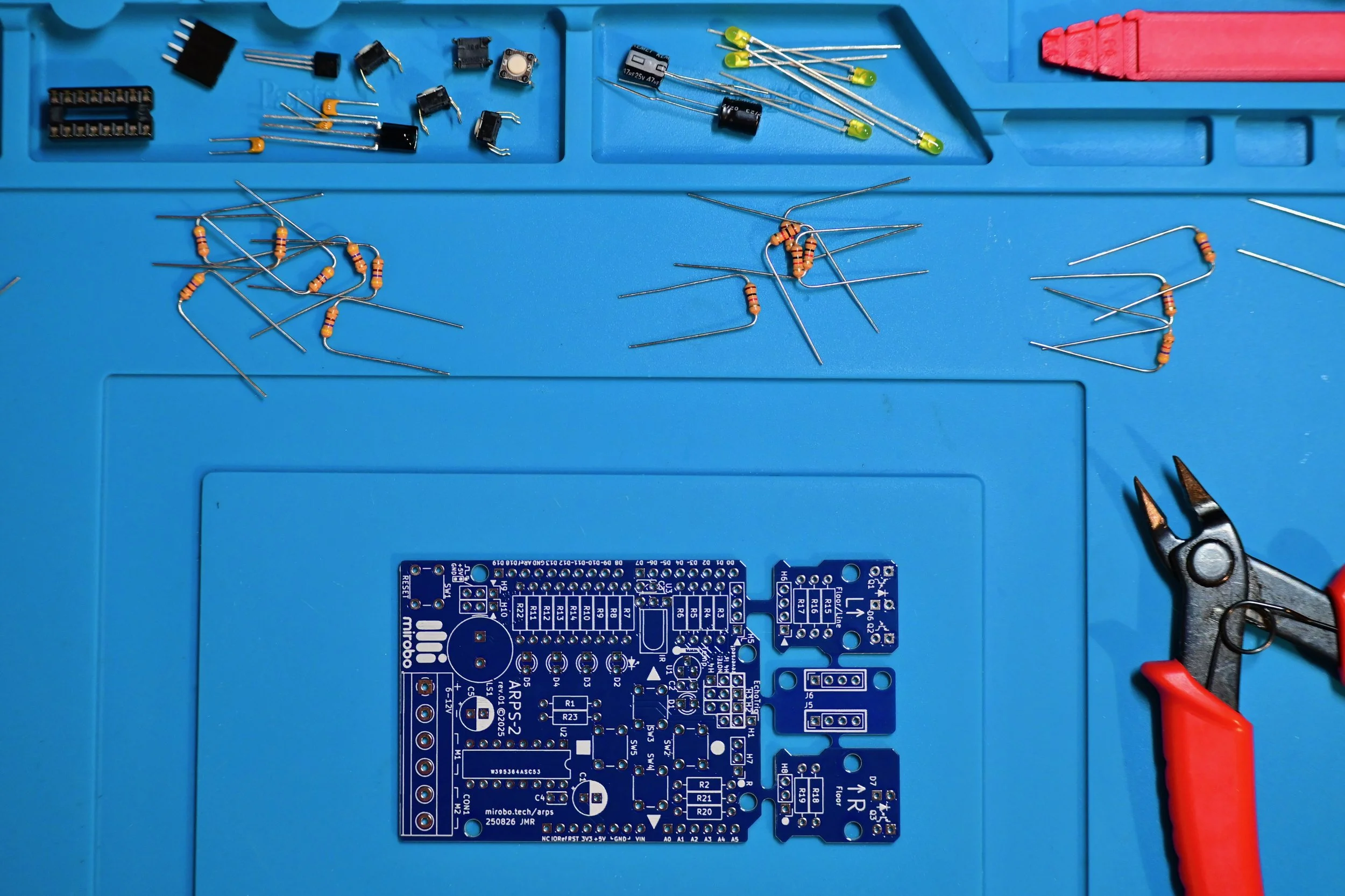
Gather all of the required tools and equipment before starting assembly of your ARPS-2. We recommend:
an electronic soldering iron with a fine tip for soldering all of the through-hole parts
electronic solder formulated with a no-clean, or water soluble flux
low-profile shear cutters to trim component leads after soldering
Step 1: Select your configuration
ARPS-2 is designed in a way that enables you to start programming without having to install all of its parts, and lets you choose its final build configuration! Use the schematic diagram and the descriptions below to help you decide which ARPS-2 configuration will work best for your intended use or application.
The components shown on the schematic without dashed lines around them are common to all build configurations, while optional components are drawn inside dashed outlines and allow you to customize your ARPS-2 to add additional features and enable expanded capabilities.

Click to view or download the full-size ARPS-2 schematic diagram (PDF).
ARPS-2 build configurations
The assembly steps will lead you through three, progressively more capable ARPS-2 build configurations: the Educational Starter configuration, the Robot Starter configuration, and a third configuration that allows you to add optional components or fully to assemble your ARPS-2.
Each build configuration is colour-coded. Select a build configuration from its description, below, then install the parts listed in the matching colour of the assembly steps.
Link text
Link text
Educational Starter configuration
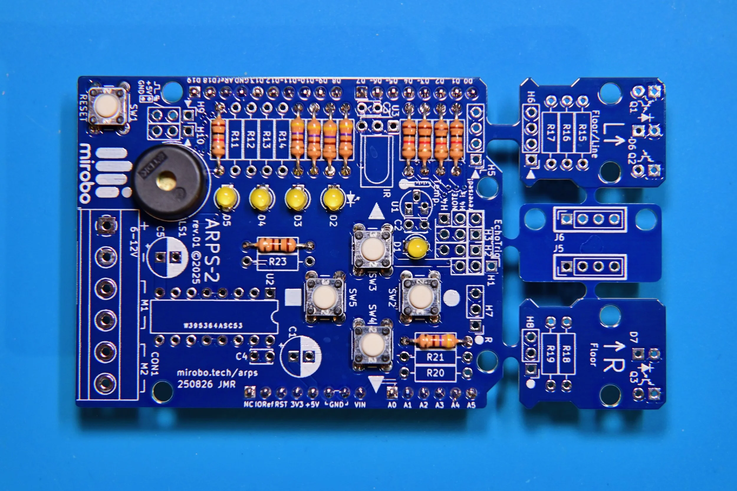
Components shown in the green assembly steps are common to all ARPS-2 configurations. Installing only the components listed in the green assembly steps completes ARPS-2 in a quick-build, minimal components Educational Starter configuration.
The Educational Starter configuration contains only the basic components needed to start learning programming using the Introductory Learning Activities.
(Note: to complete ARPS-2 Introductory Learning Activity 5 - Analog Input, you will also need to install one or more of the optional analog circuits: analog temperature sensor U1, battery voltage divider resistors R20 and R21, or optical floor sensor LEDs and phototransistors D6 and Q1 or Q2, or D7 and Q3.)
Robot Starter configuration
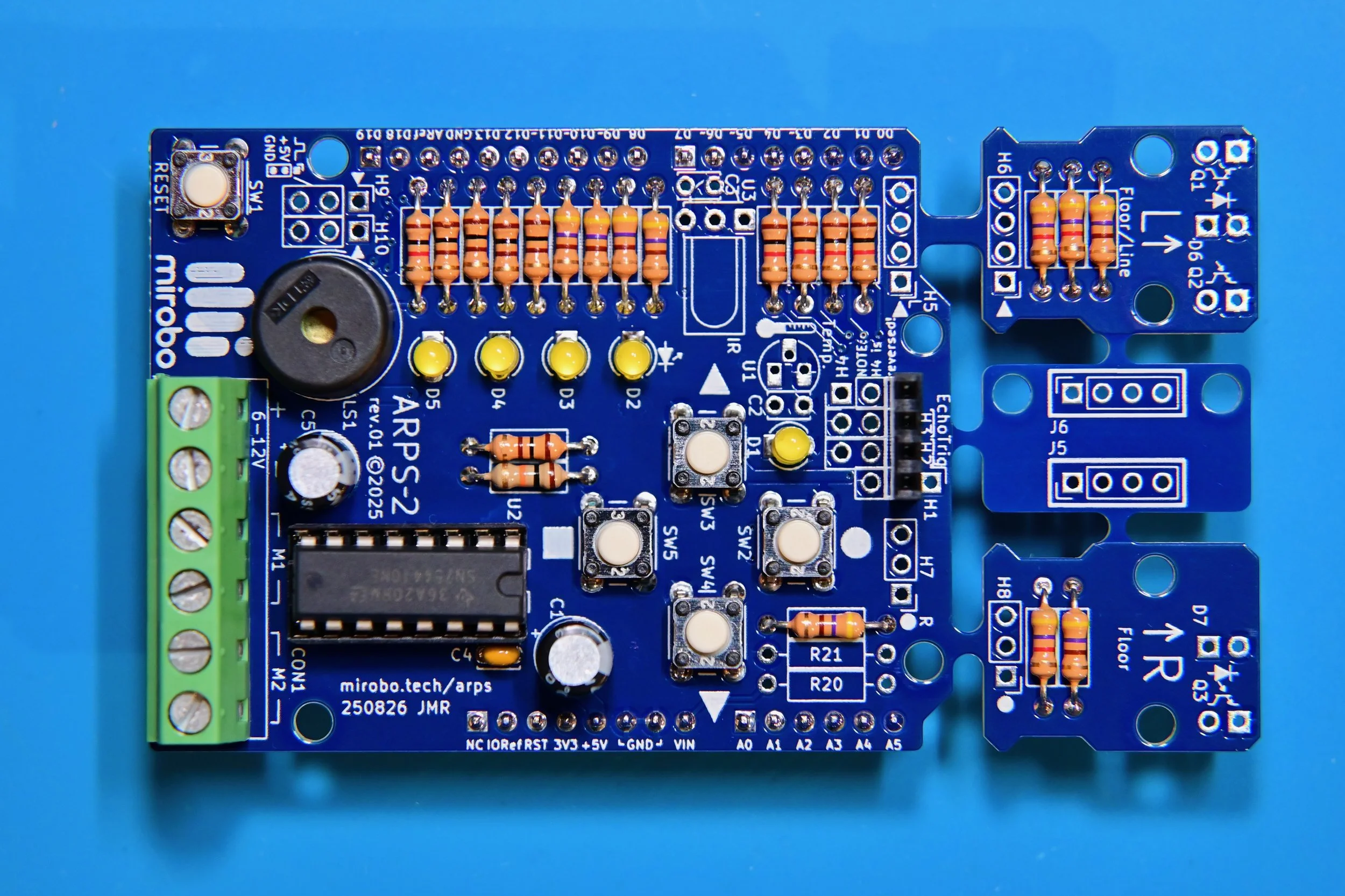
Follow both the green and red assembly steps to build ARPS-2 in its Robot Starter configuration. The Robot Starter configuration includes the components needed to build ARPS-2 into a simple line-following or floor sensing robot.
(Note: in this configuration you’ll need to decide how to populate headers H1 - H4 to support any additional sensors your robot might need. Installing a 4-pin header socket makes it easy to mount an HC-SR04 SONAR module directly on-board, while installing header pins makes connecting external I/O devices or the extension header PCB easier.)
Optional/Full Build configuration
Optional sets of components can be added to either starter configuration of ARPS-2 at any time to enable additional features and capabilities.
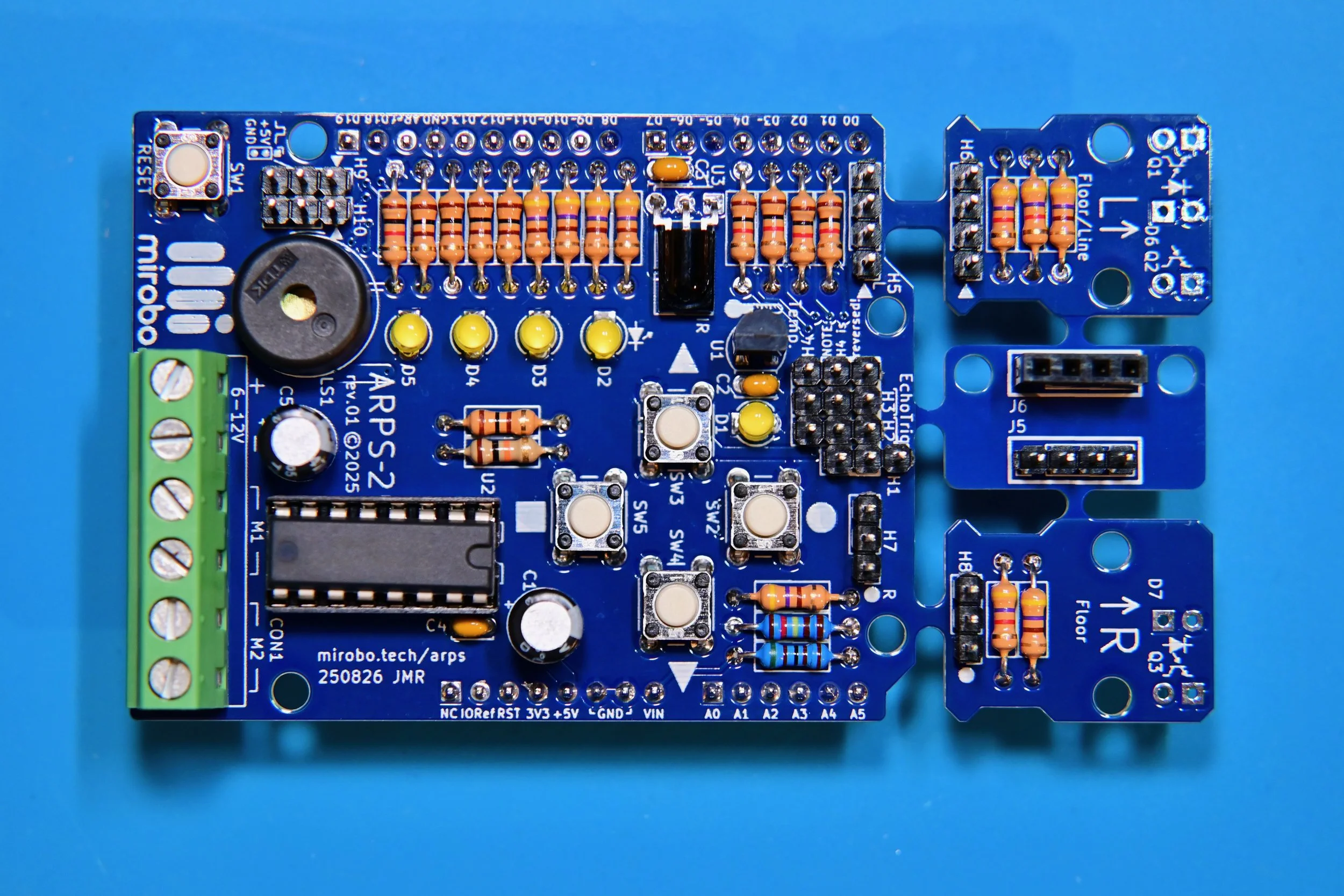
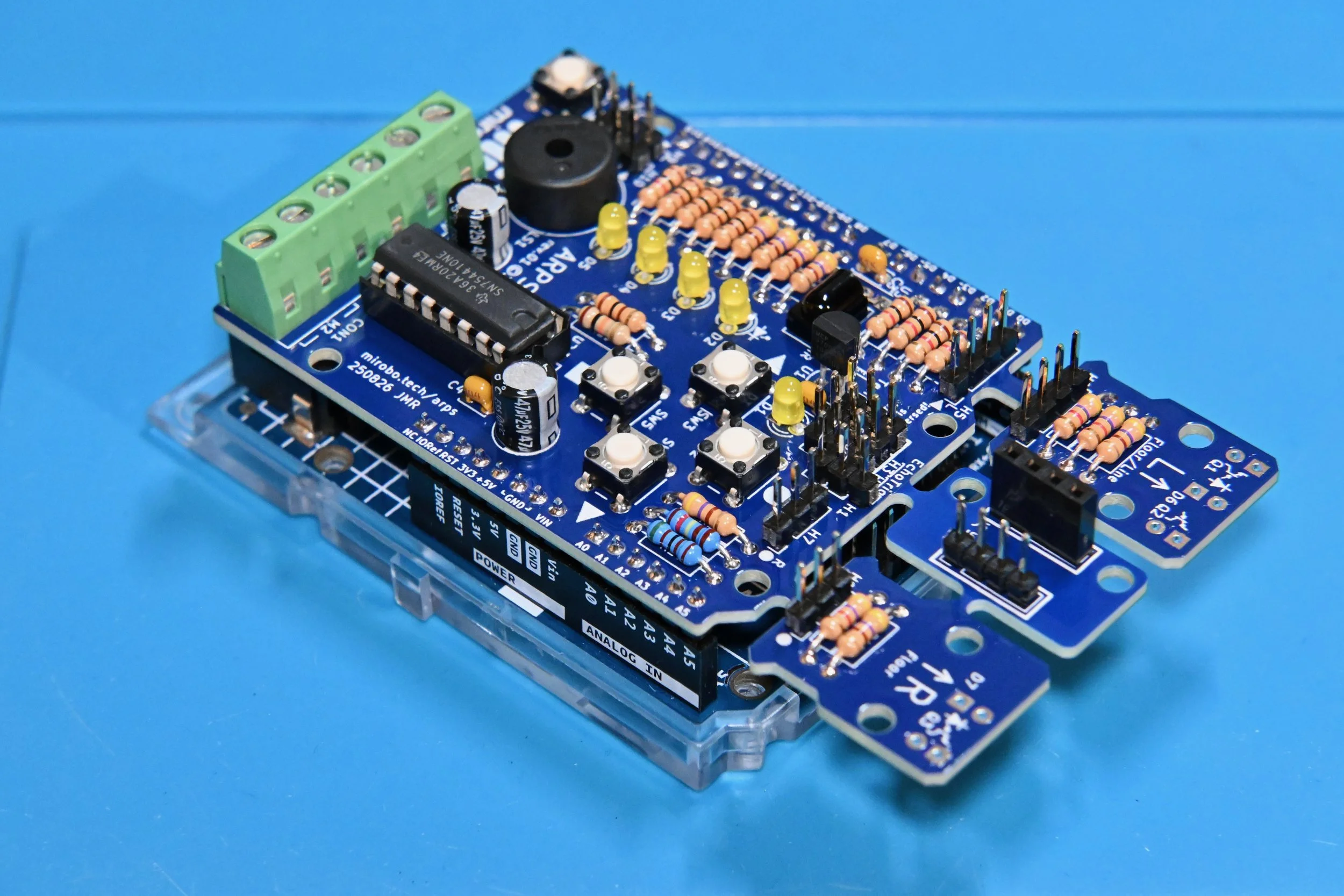
This fully-assembled ARPS-2 has an optional temperature sensor, battery voltage divider resistors, IR demodulator, and extra I/O headers for external sensors or servos installed. Follow the blue assembly steps to install the desired optional components and customize ARPS-2 for your application.
Step 2: Check your components
The ARPS-2 kit comes with all of the electronic components needed to fully populate the ARPS-2 PCB (Printed Circuit Board), including the LEDs and phototransistors used to assemble the break-away optical floor and line sensor modules. The kit does not include the extension cables required to remotely mount the optical sensor modules or the extension header PCB.
Use the parts list, linked above, to verify that you have all of the required electronic components, or to order the components you need if you have obtained a bare ARPS-2 printed circuit board.
Additional required ARPS-2 components
The kit does not include an Arduino® UNO microcontroller. To start programming using ARPS-2 you will need:
an Arduino UNO R4 Minima microcontroller (recommended), or
an Arduino UNO Rev 3 (prevents pushbuttons SW2 and SW3 from working)
an appropriate USB 2 cable to connect your Arduino to your computer or Chromebook
Optional ARPS-2 add-on components
ARPS-2 is designed to connect to a variety of external devices, including:
an HC-SR04 or HC-SR04P ultrasonic SONAR distance sensor module
two low-current (under 500mA), 6-12V DC gear motors (with bi-directional control), or up to four DC motors (single direction only), or one bi-polar stepper motor
up to six 5V hobby servos or other 3-pin digital I/O devices
up to two 3-pin analog input devices
an external 6-12V battery or battery holder
0.1” socket extension cables (sometimes called DuPont connectors/cables) to connect the two break-away optical sensor modules and extension header PCB that come as part of the ARPS-2 PCB
Step 3: Start assembling your ARPS-2
To make the manual assembly of PCBs easier, electronic components are often installed in order from the physically smallest to the tallest. The assembly steps below mostly adhere to this convention.
Each set of optional components in the blue steps can be installed at any time, but following the order of the assembly steps may make the installation of some components easier than installing them later. So, if you think your ARPS-2 might need a particular component later, it may be better to install it during its installation step.
Follow the colour-coded assembly steps for the two ARPS-2 starter configurations and the full build:
green, to install the common components that make up the Educational Starter configuration
green and red to build a bare minimum robot controller for the Robot Starter configuration
blue to add optional circuits, extra capabilities, or to fully assemble ARPS-2
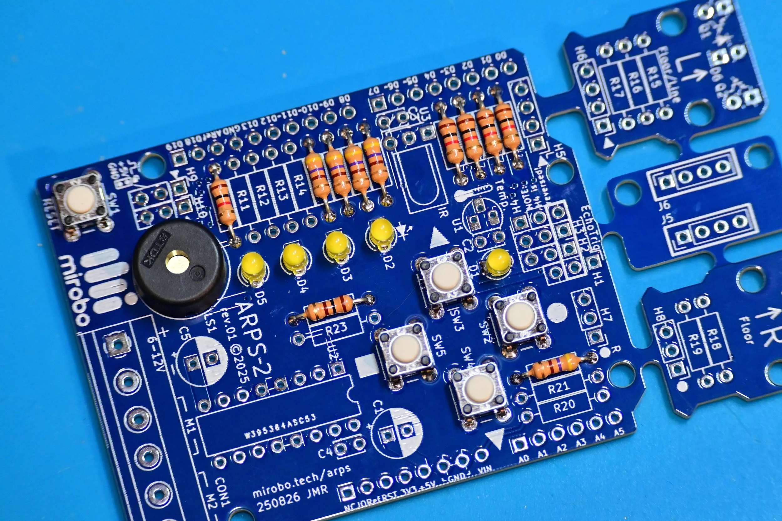
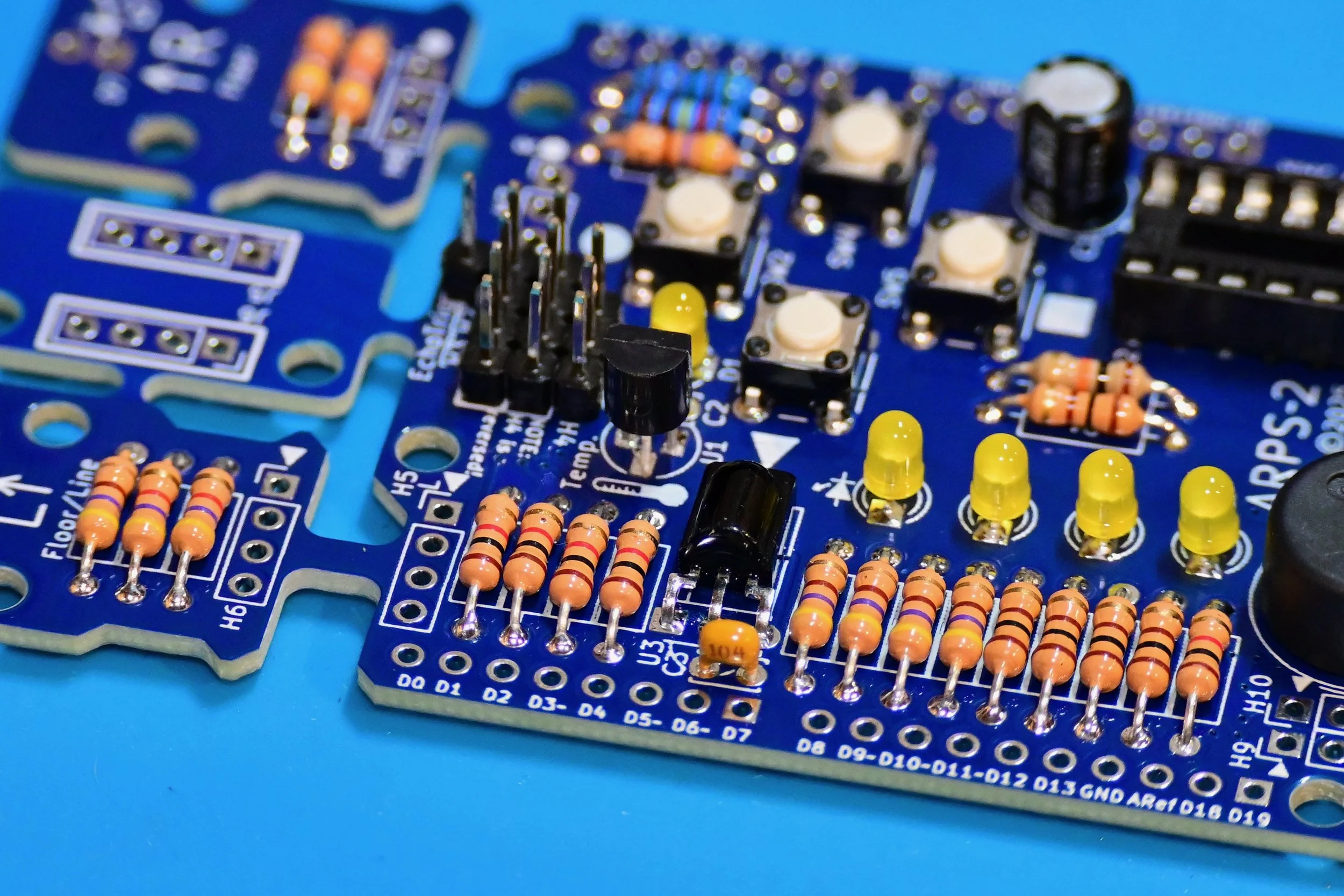
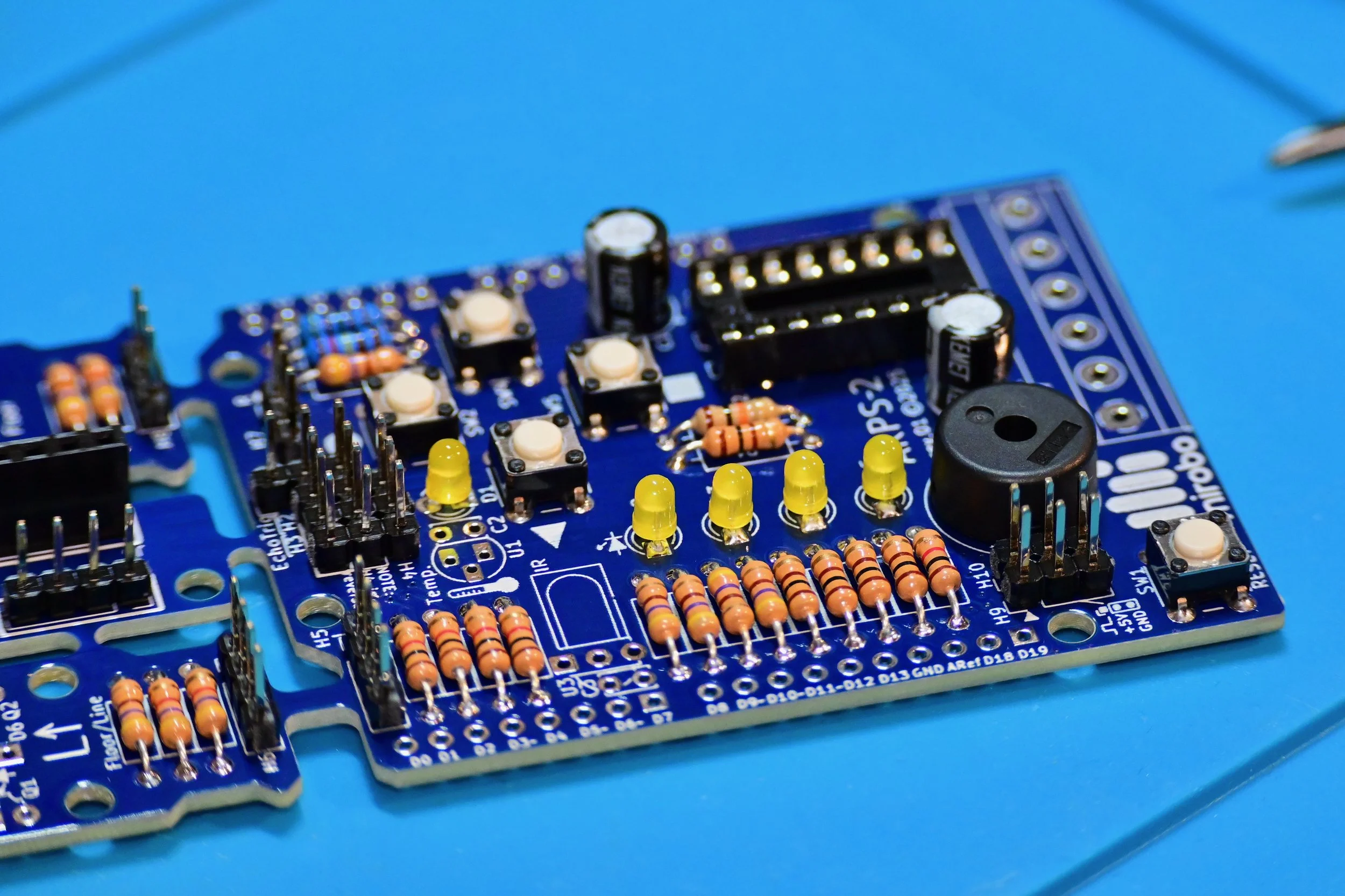
User I/O device resistors
Resistor installation tip: pre-bend the resistor leads to make it easier to install the resistors in the PCB.
Install 100 Ω resistor R1 for the RESET pushbutton circuit.
Install 1.0 kΩ pushbutton series current-limiting resistors R3, R4, R5, and R6.
Install 1.0 kΩ piezo load resistor R22.
Install 470 Ω LED series current-limiting resistors R2, R7, R8, R9, and R10.
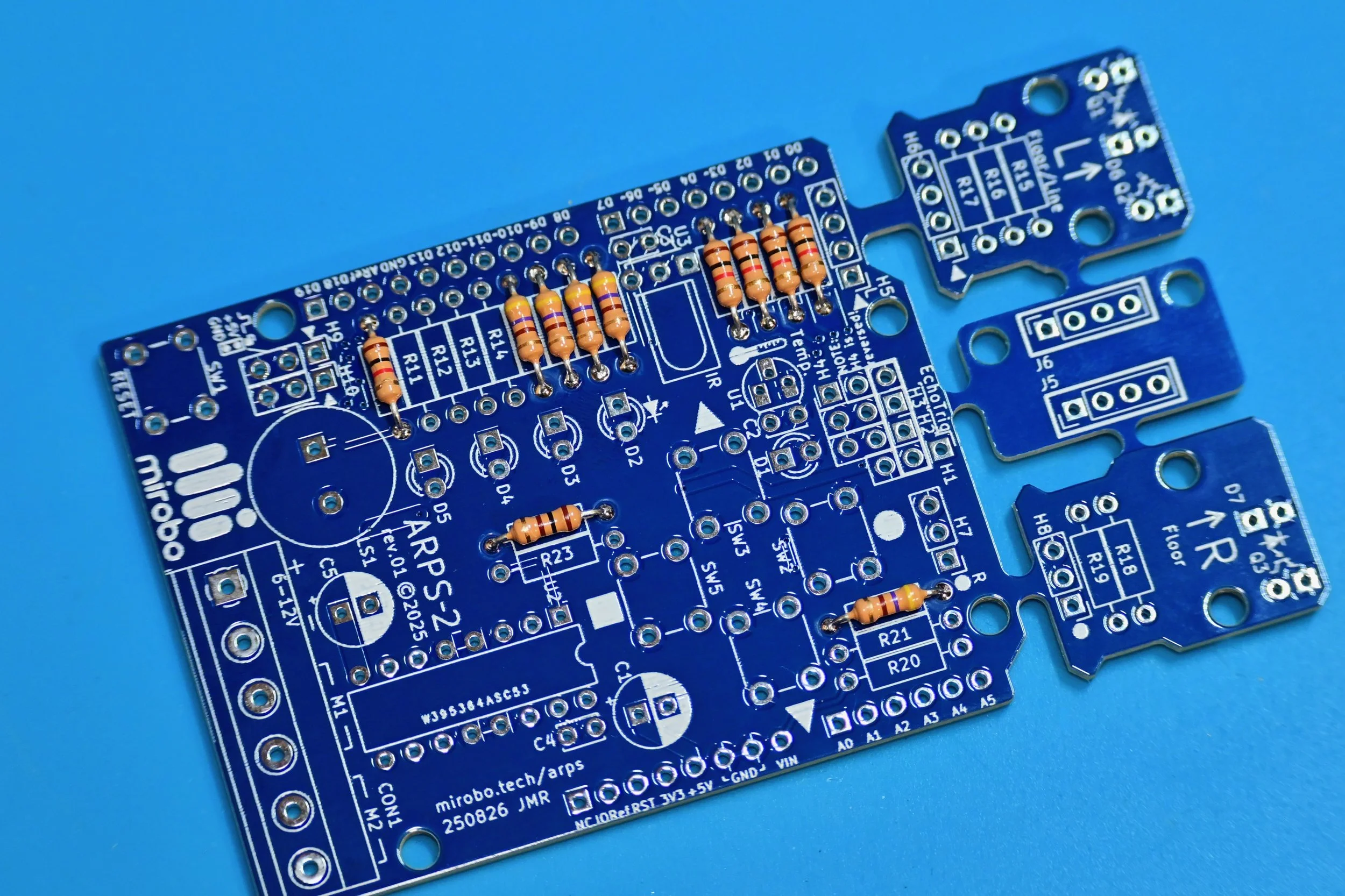
Analog input/digital I/O expansion header series resistors
Install 100 Ω series resistors R11, R12, R13, and R14 to connect Arduino UNO to expansion headers H1-H4.
A header socket for an ultrasonic SONAR distance sensing module will be added across H1-H4 in a later step for the Robot Starter configuration. Alternatively, individual 3-pin headers can be installed instead of the header socket to make it easier to connect external 5V I/O (Input/Output) devices.
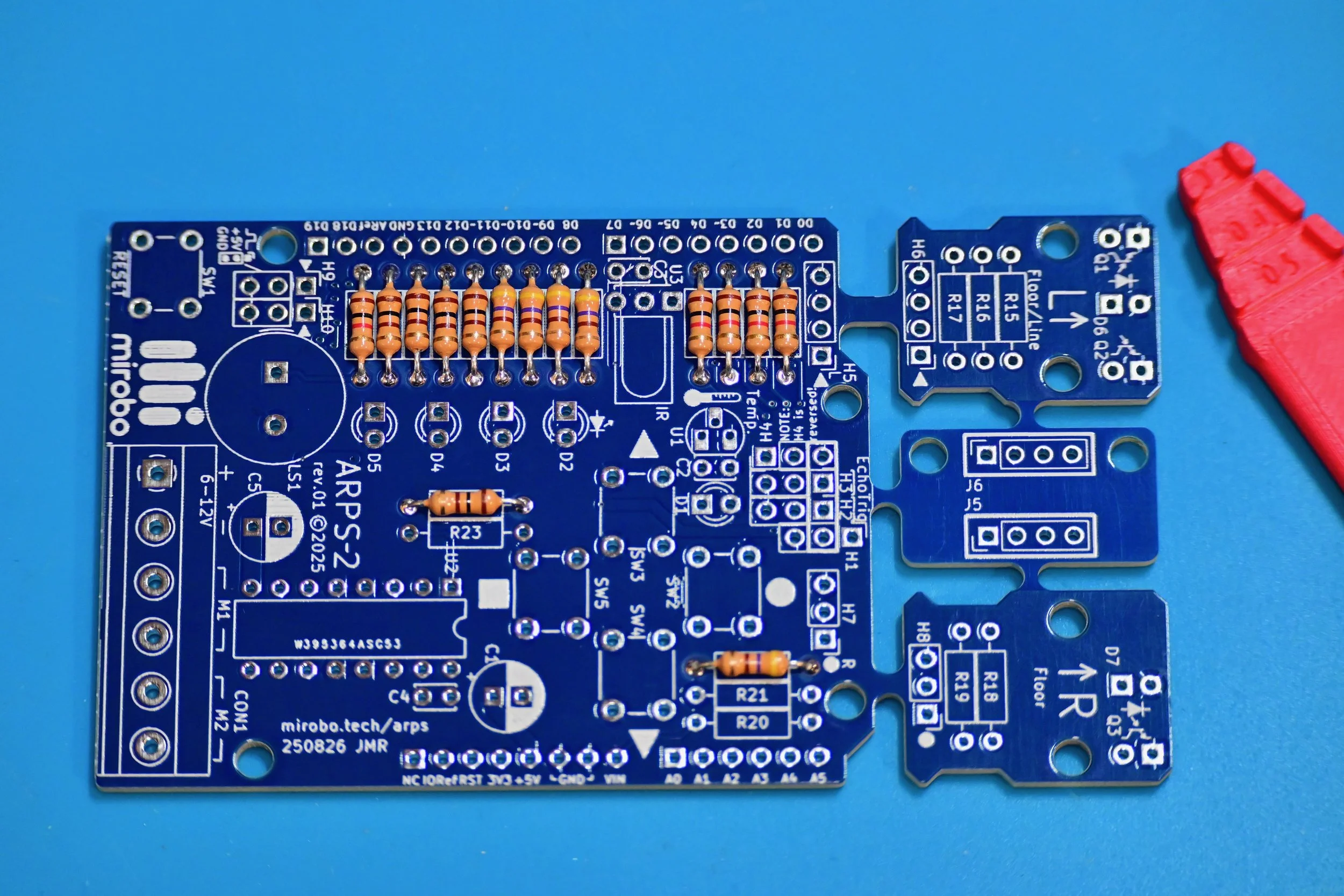
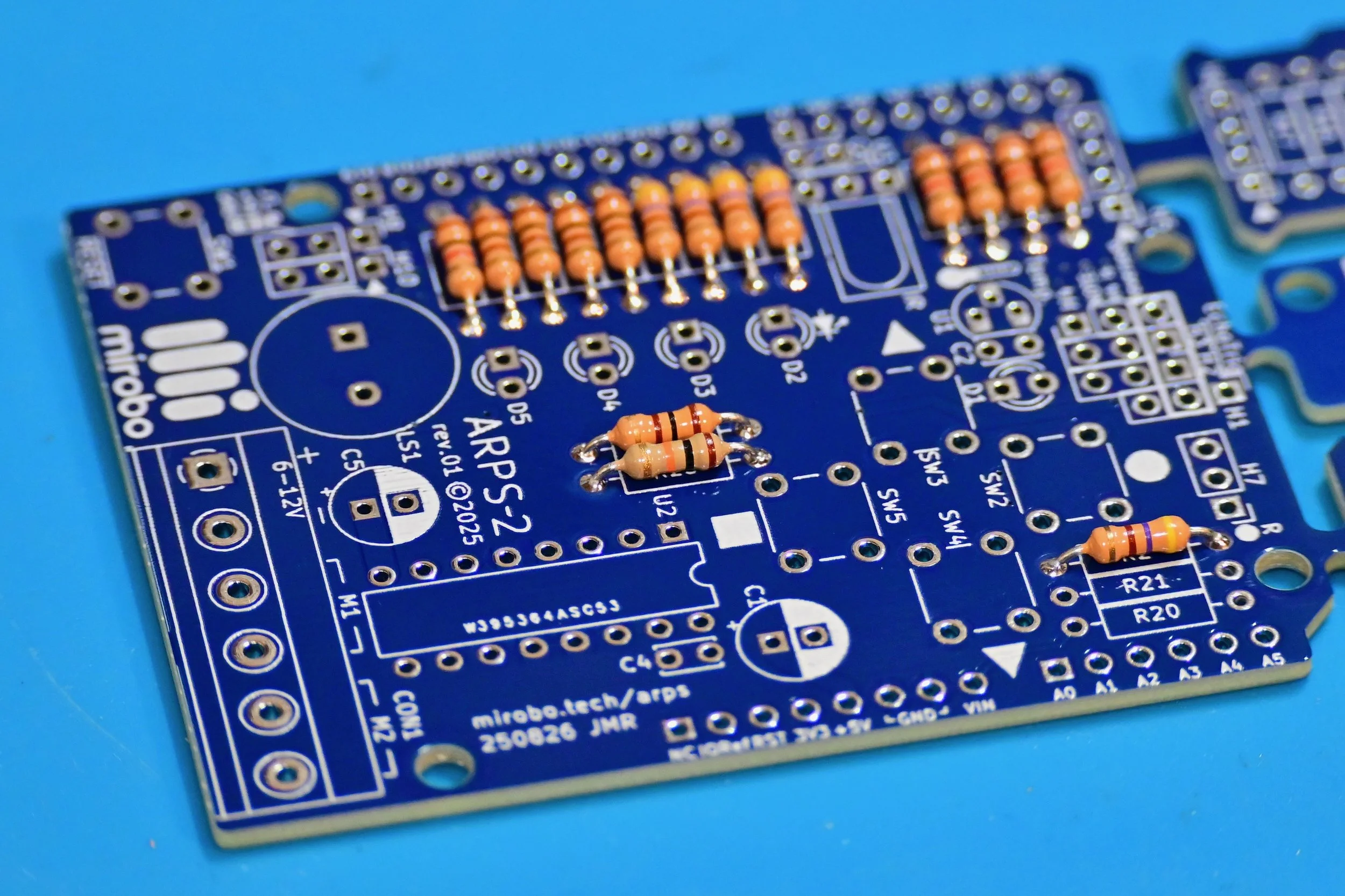
Motor driver pull-up resistor
Install 10 kΩ pull-up resistor R19. This pull-up resistor enables the motor outputs on motor driver IC U2.
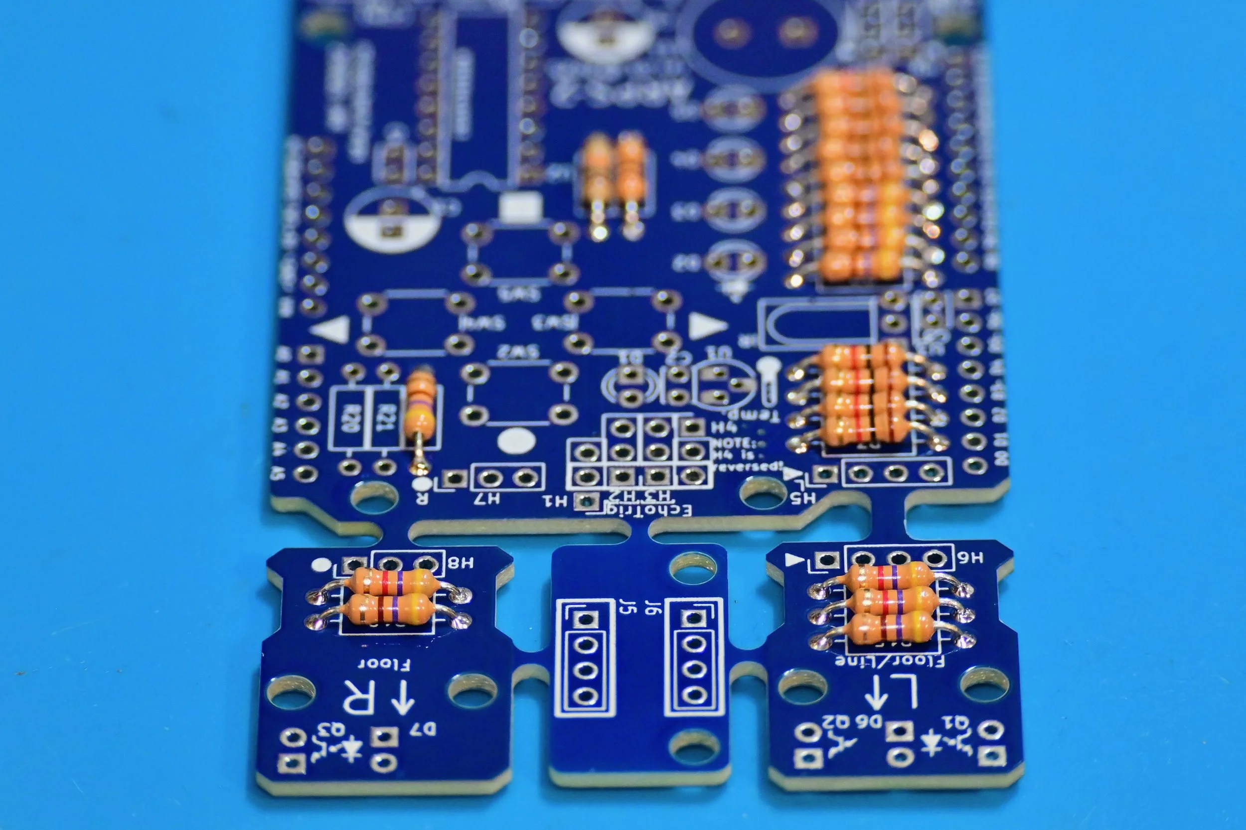
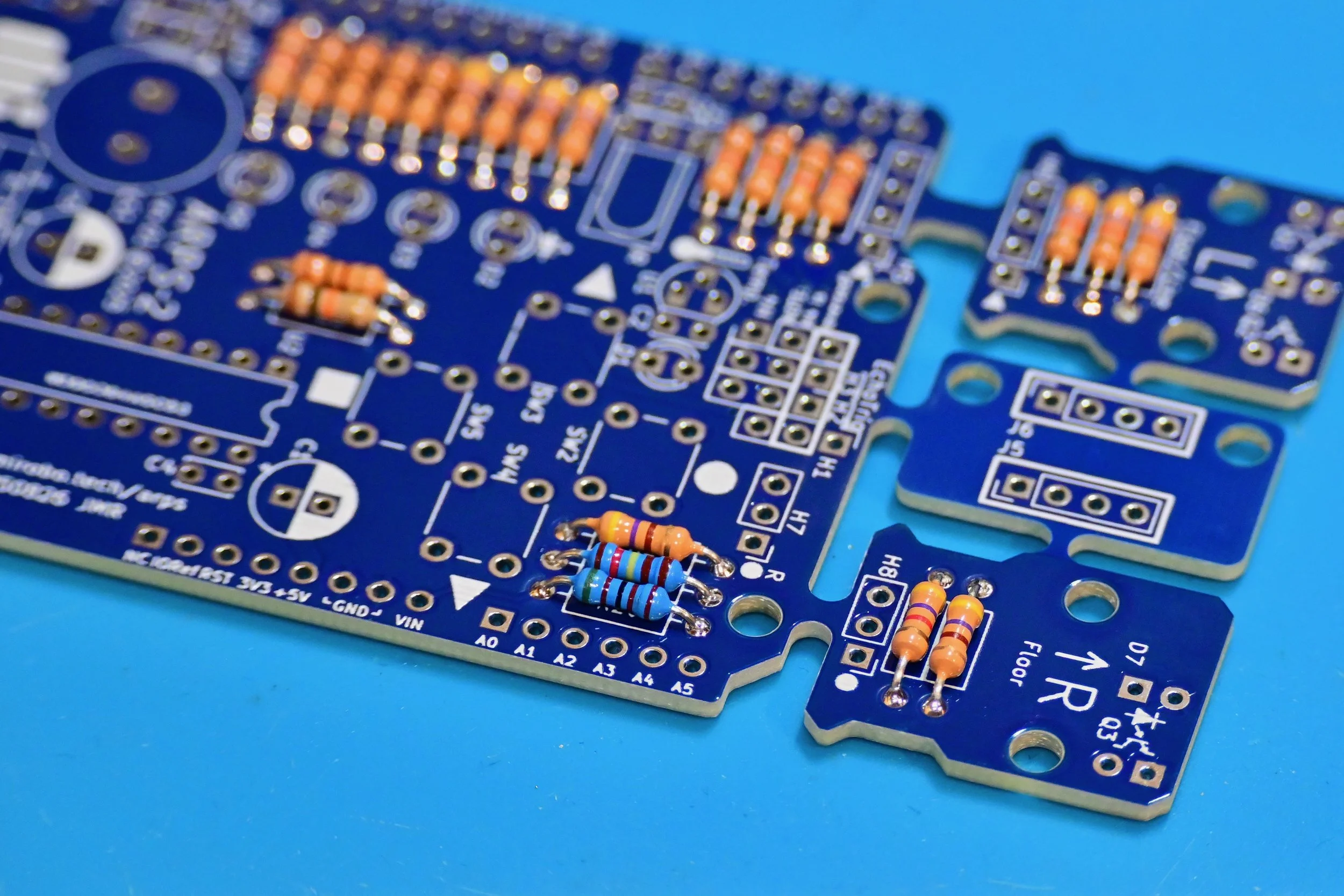
Optical floor sensor resistors
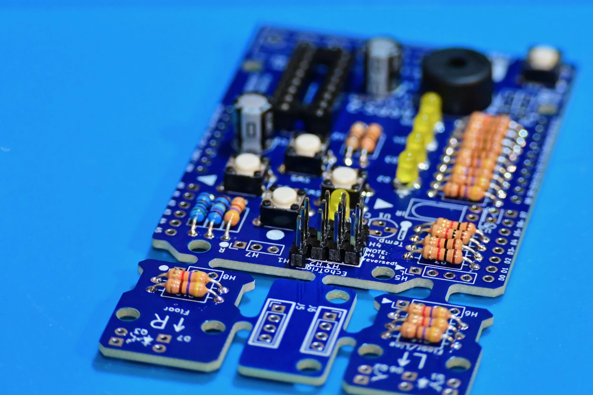
ARPS-2 features break-away left and right (labelled L and R) optical sensor modules making it easy to create robot floor, wall, or line sensors. Each optical sensor module can remain attached to the main ARPS-2 PCB, or they can be broken away and re-attached using extension cables connected between headers H5 and H6, and H7 and H8.
Install 470 Ω LED series current limiting resistors R15 and R18 for floor illumination LEDs D6 and D7.
Install 4.7 kΩ phototransistor pull-up resistors R16, R17, and R19 for phototransistors Q1, Q2, and Q3.
The LEDs and phototransistors should only be installed after mounting the sensor modules on a robot.
Optional voltage divider resistors
These resistors form a voltage divider to reduce the battery potential to less than 5V, allowing Arduino UNO to safely sense the external battery potential.
Install 5.1 kΩ 1% resistor R20.
Install 1.24 kΩ 1% resistor R21. Note: This resistor is supplied as part of the kit and provides the maximum battery voltage input range when using Arduino UNO R3. See the schematic diagram for other resistor values that can provide better voltage resolution over smaller ranges or are a better match for Arduino UNO R4.
Install the pushbuttons
Install RESET pushbutton SW1, and user pushbuttons SW2, SW3, SW4, and SW5.
Installation tip: most pushbuttons already have fairly short leads, but they can be sharp. Trimming the leads after soldering will make the PCB easier to handle.

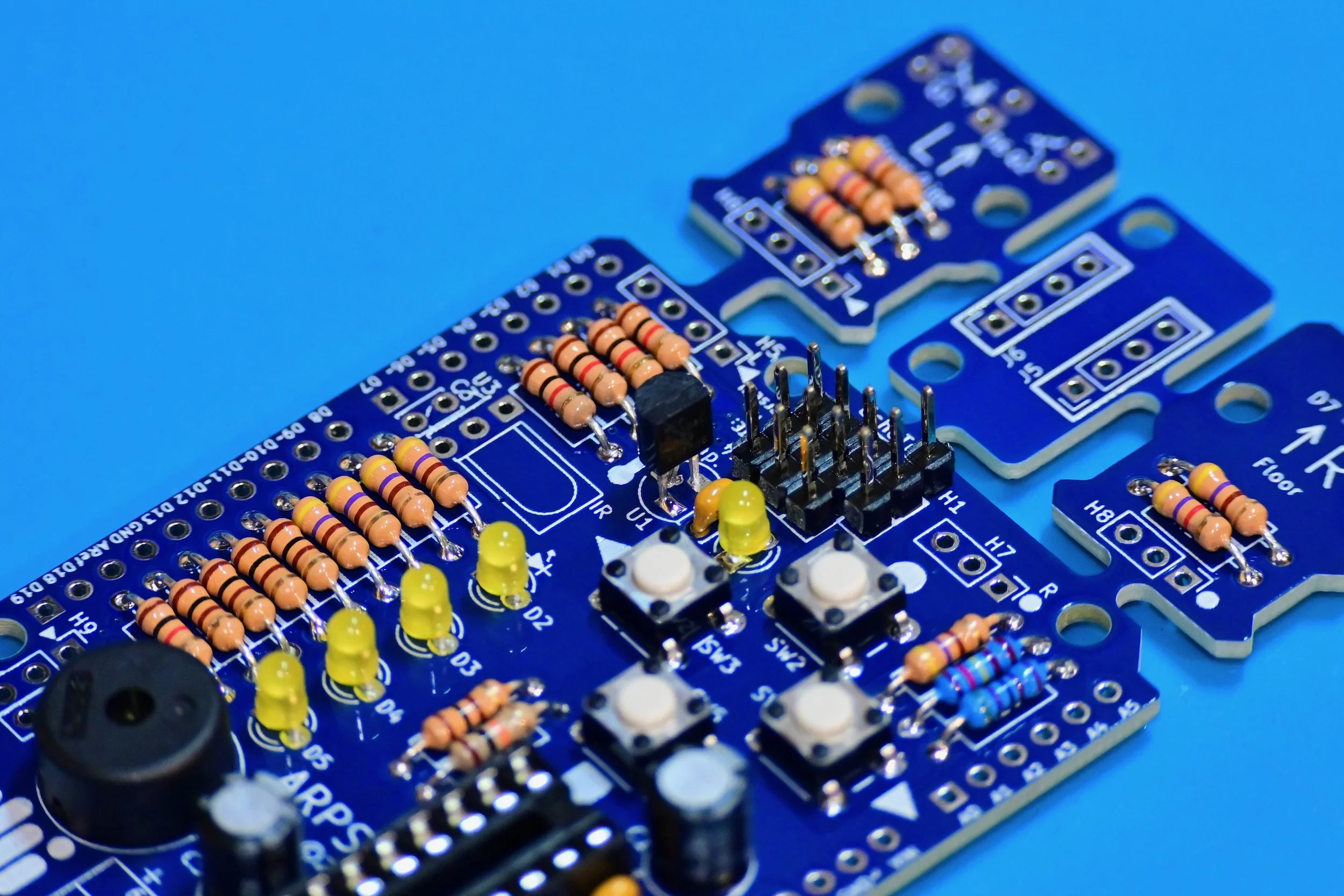
Install the piezo speaker and LEDs
Install piezo speaker LS1.
Kits are normally supplied with a non-polarized speaker so its orientation in the PCB does not matter. If a polarized buzzer is used instead, install the positive terminal into the square pad closest to the silkscreen legend H10.
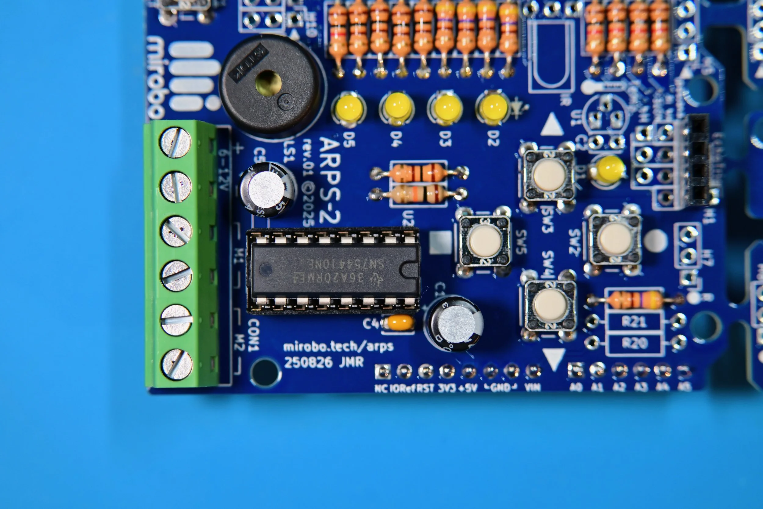
Install power LED D1 and user LEDs D2, D3, D4, and D5. All LEDS must be installed with their long leads inserted into the square PCB pads and their short leads inserted into the round PCB pads.
(This is opposite to common PCB practice but was done for simplicity and commonality with other components having different length leads (electrolytic capacitors and phototransistors), which helps to reduce problems for new learners in a classroom setting. The small schematic symbols on the silkscreen beside the LEDs and phototransistors show the proper polarity.)
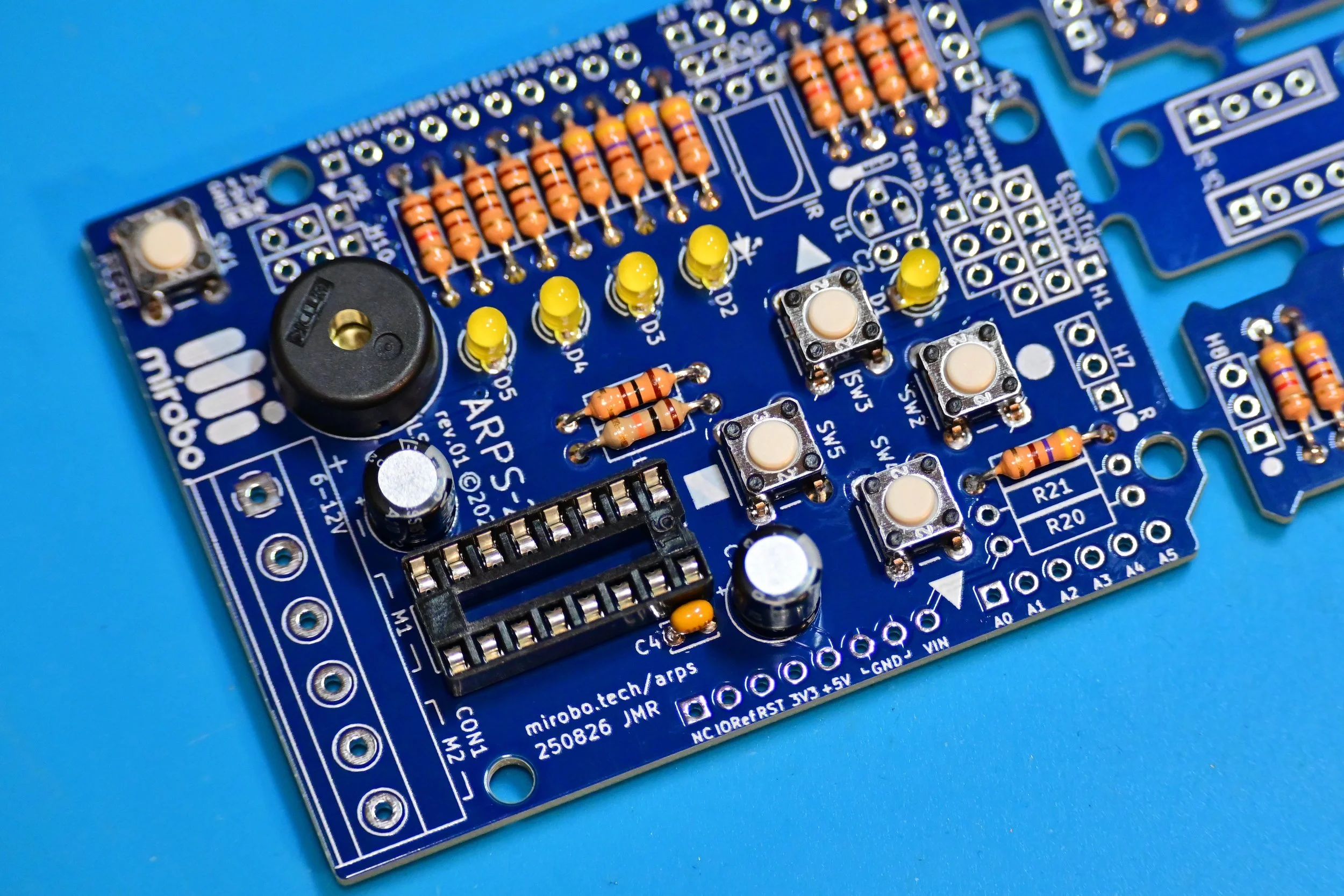
Motor driver IC circuit components
Install a 16-pin DIP IC socket for motor driver IC U2 when ARPS-2 is used in educational settings, or when using low current DC motors. (Since the PCB ground plane acts as a heat sink, it is better to solder the motor driver IC directly into the PCB when using high current motors – although this makes replacement in the event of a motor driver IC failure much more difficult).
Install 100 nF decoupling capacitor C4 beside the IC socket.
Install 47 µF electrolytic filter capacitors C1 and C5 with their long leads inserted into the square PCB pads. (The negative polarity stipe on the capacitor must align with the filled half of the capacitor silkscreen outline on the PCB.)
Distance sensor module header socket
Install the 4-pin header socket if you plan to mount an ultrasonic SONAR distance sensor module directly onto the main ARPS-2 PCB. The socket bridges across headers H1-H4, as indicated by the slightly thicker rectangular outline parallel to the edge of the PCB.
Alternatively, header pins can be installed into each of the H1-H4 headers (as shown in the next step). The 4-pin header socket can also be mounted into J5 or J6 on the header extension PCB allowing the SONAR module to be mounted away from the main ARPS-2 PCB.
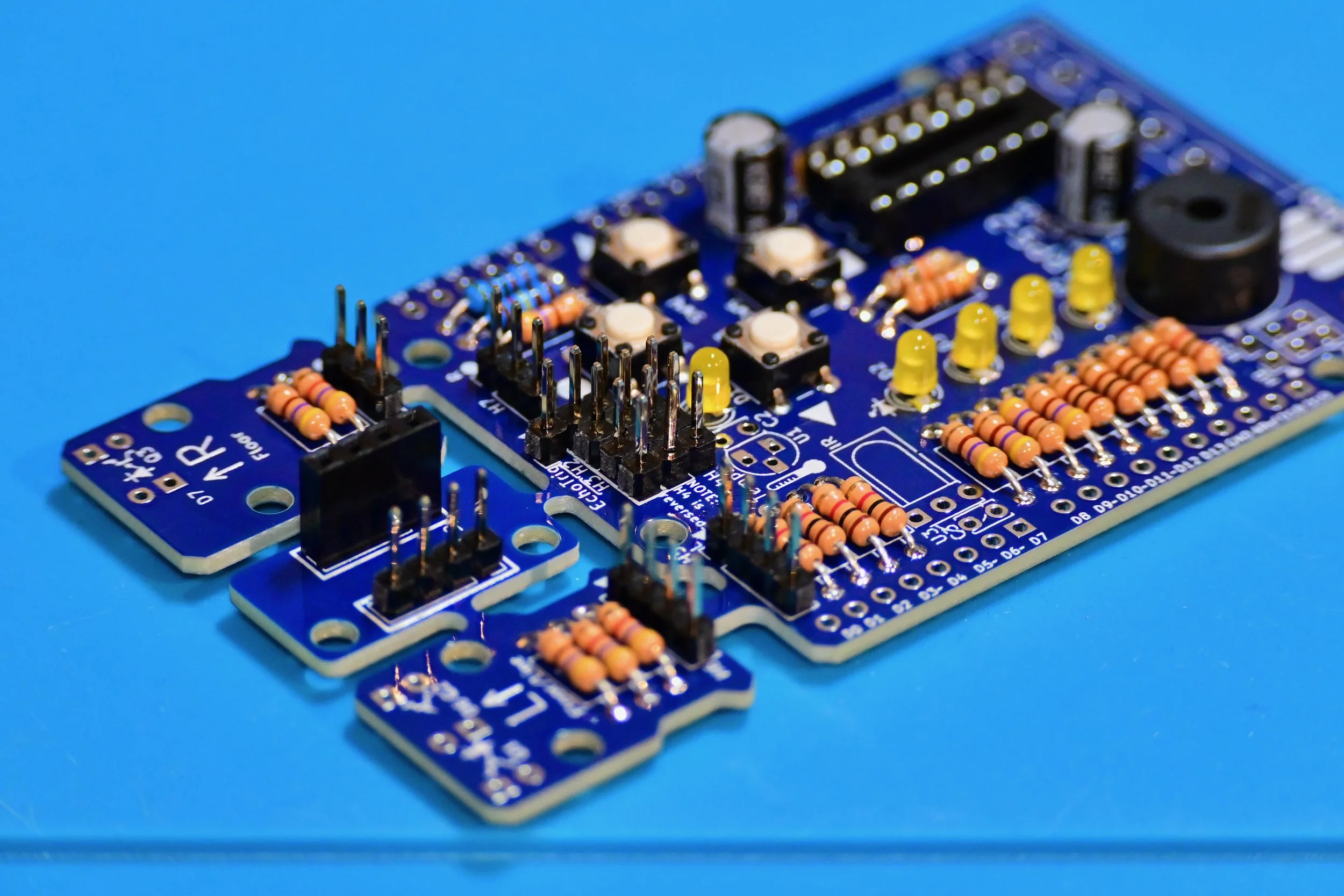
Optional I/O header pins
If the ultrasonic SONAR distance sensor module will not be mounted on the main ARPS-2 PCB, then 3-pin analog/digital I/O headers can be installed into one or more of the H1-H4 header positions. Break the smaller 40-pin header into the required number of 3-pin header strips.
Even if the 4-pin header socket was installed in the previous step, the signal pins of headers H1 and H4, as well as the unused +5V and ground pins of H2 and H3 can be used by other circuitry. These can be accessed by installing individual header pins, or pairs of header pins, in the empty pads beside the header socket.
Optional temperature sensor
The analog temperature sensor enables ARPS-2 to measure temperatures from -40°C to +125°C.
Install temperature sensor U1, matching its orientation to the silkscreen image.
Install 100 nF filter capacitor C2.
Optional IR (infrared) demodulator
The IR demodulator can be used to decode signals from an IR remote control or another Arduino circuit, and enables ARPS-2 to respond to wireless optical transmissions.
Bend the leads of IR demodulator U3 backwards and install it laying flat on the ARPS-2 PCB with its circular lens facing up.
Install 100 nF filter capacitor C3.
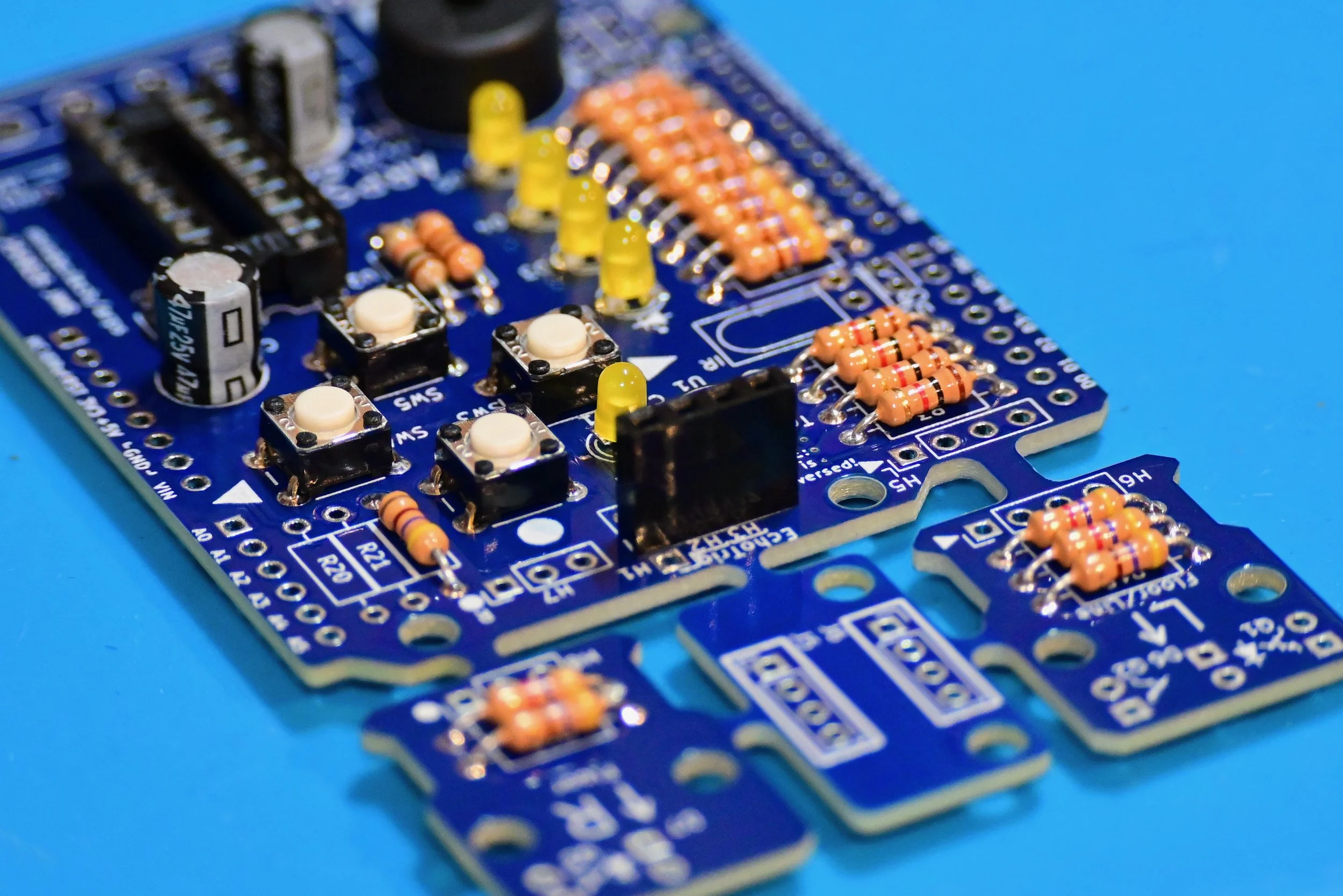
Optional optical floor sensor headers
The LEDs and phototransistors in the L (left) and R (right) optical sensor modules are electrically connected to the main ARPS-2 PCB while the modules remain physically attached. If the sensor modules are snapped off, jumper wires between 4-pin headers H5 and H6, and 3-pin headers H7 and H8, can be used to electrically reconnect the sensor modules to the main ARPS-2 PCB.
Install 4-pin headers H5 and H6 to allow for re-connection of the L floor sensor module.
Instal 3-pin headers H7 and H8 to allow for re-connection of the R line/floor sensor module.
Optional 5V digital I/O headers
Install 3-pin digital output headers H9 and H10 to connect external digital devices or servos.
Ensure that both 47 µF capacitors C1 and C5 are installed if servos will be connected to H9 or H10.
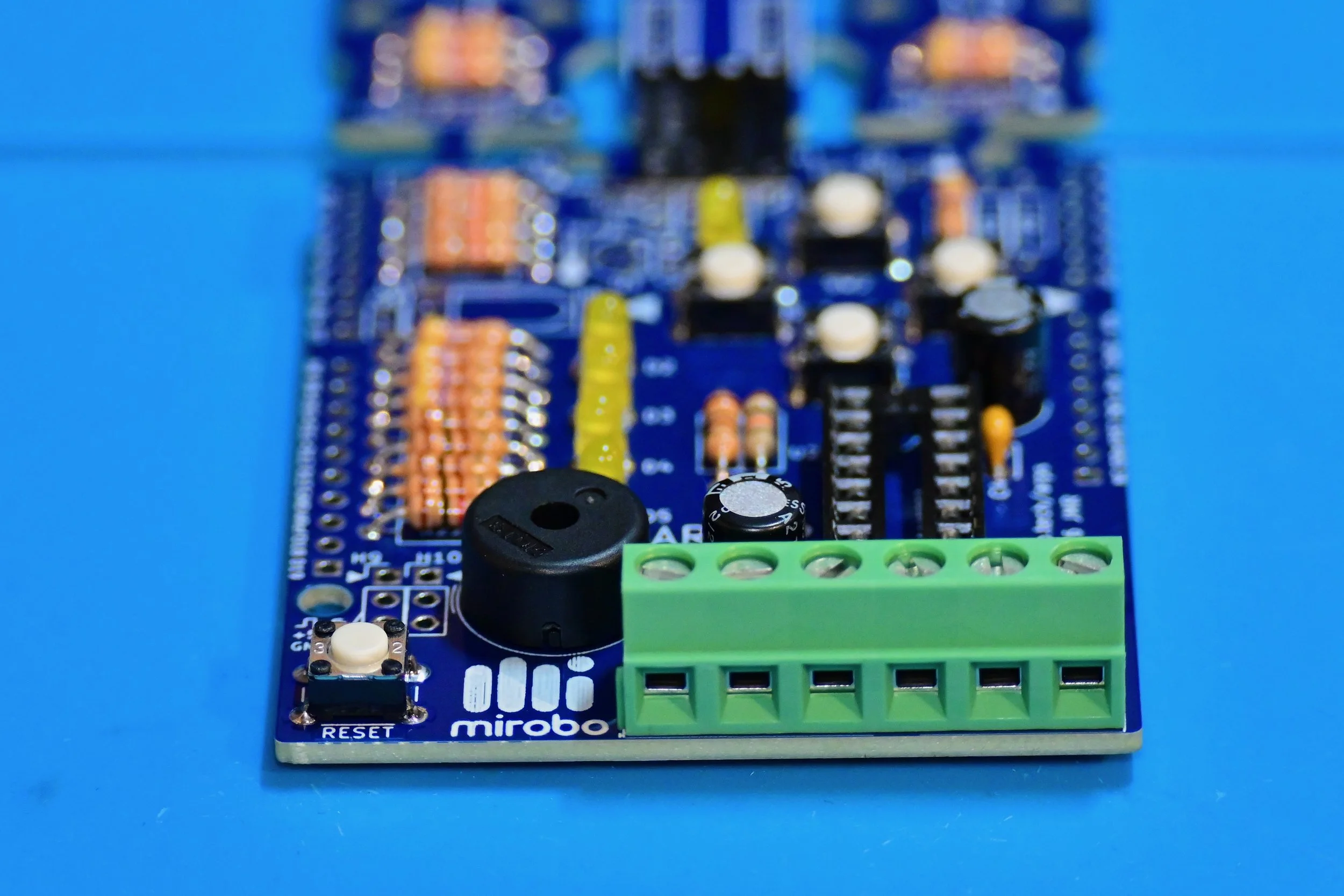
Install the screw terminal strip
Install screw terminal strip CON1, ensuring its wire entry openings face the outside edge of the PCB.
At this point, the Robot Starter configuration is complete except for the Arduino headers (installed in the next step) and the optical floor and line sensor LEDs and phototransistors. The LEDs and phototransistors must be positioned at the proper height for maximum sensitivity and should only be installed after the optical sensor modules are mounted on the robot chassis.
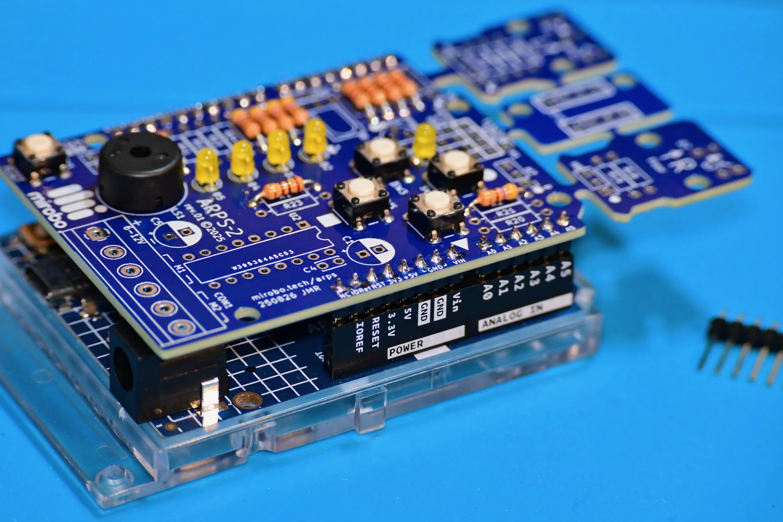
Arduino UNO header pins
Break the larger 40-pin header strip into one 6-pin strip, two 8-pin strips, and one 10-pin strip. Insert the long pins of each strip into the matching sockets of an Arduino UNO. Align ARPS-2 on top of the short pin ends sticking out of the Arduino UNO and carefully solder each header pin on the top of the ARPS-2 PCB.
At this point, the assembly of ARPS-2 is complete! Carefully remove ARPS-2 from your Arduino, then inspect all of its solder connections. Fix any poor solder connections or solder shorts between component leads. Clean the circuit board using the recommended flux remover for the type of solder used during assembly, and allow the PCB to fully dry before testing your circuit.
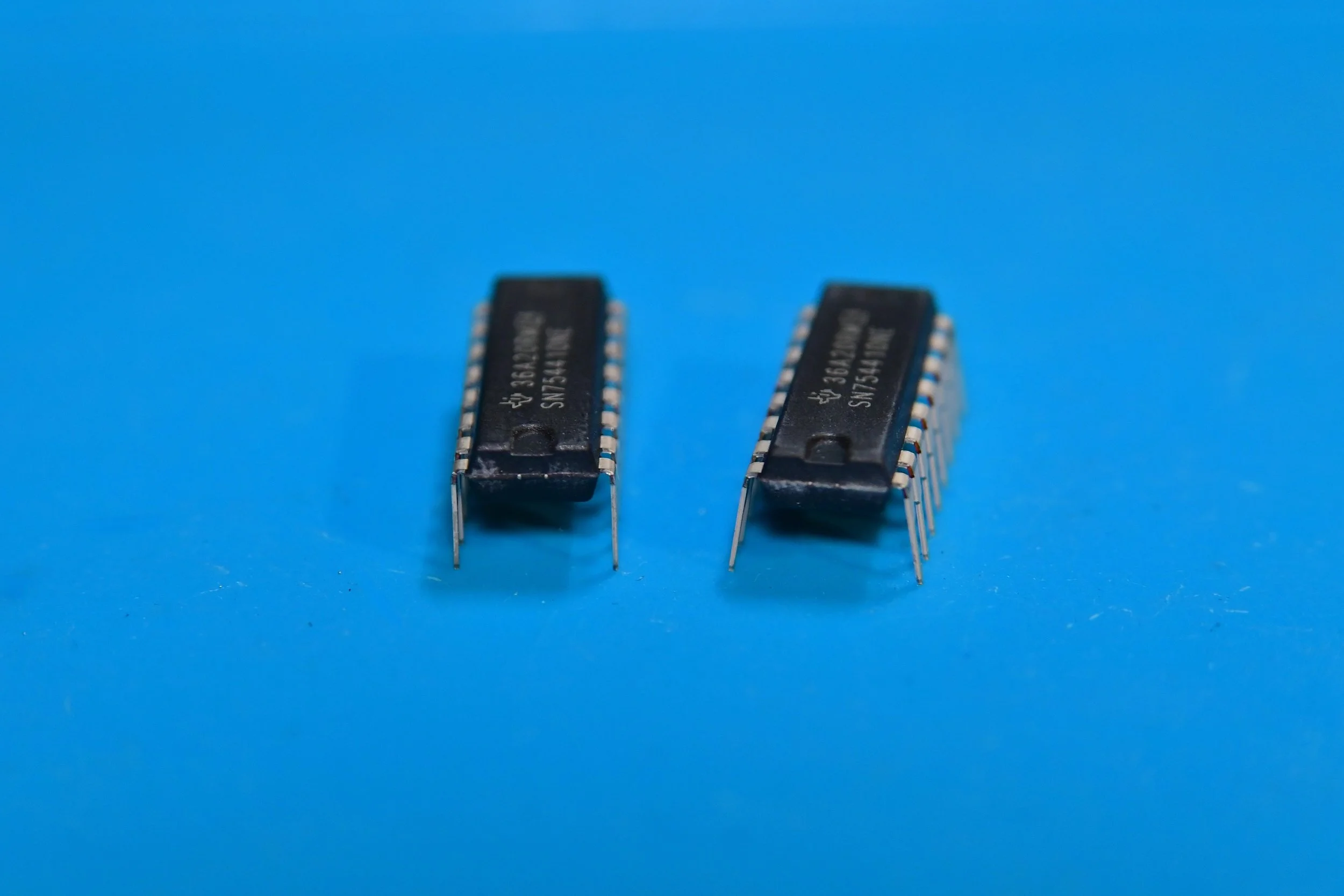
Prepare the motor driver IC for installation
Prepare the motor driver IC (Integrated Circuit) for installation into its socket by straightening its pins so that they face directly downwards, at a 90° angle perpendicular to the IC body as shown by the motor driver IC on the left.
This is easy to accomplish by laying each row of IC pins flat against a solid work surface and applying steady downward pressure to the IC body while carefully rolling the IC body to be perpendicular to the work surface.
Install the motor driver IC
Match the notch, or the pin 1 identification dot of (if present) of the motor drive IC to the notch molded into the IC socket.
Insert the motor driver IC into its socket, carefully aligning each of its leads between the dual metal contacts in each row of the IC socket. When all of the IC’s leads are properly aligned, firmly press the IC into the socket.
Attach ARPS-2 to your Arduino UNO
Carefully align the header pins on the bottom of ARPS-2 with the header sockets on Arduino UNO, and gently push them together. Check that you have trimmed all of the component leads short enough that none of them are touching any parts of Arduino UNO – especially the USB socket on UNO R3.
The left (L) and right (R) break-away optical floor modules as well as the header extension PCB can remain attached to ARPS-2 until they are needed. Or, break them away by bending all three of them upwards, or by cutting the joining PCB material with sharp cutters.
Arduino® is a registered trademark of Arduino AG.