
UBMP4 Introductory Programming Activity 2
Variables and constants
The Intro-1-Input-Output program demonstrated how to read inputs and control outputs. In that activity, the actions of reading the pushbutton inputs and lighting the corresponding LED outputs happened immediately. But, what if you wanted to wait for a number of input events before activating the output, or repeat the output actions a number of times instead? One way to do this is with a software variable – they enable your program to keep track of things by storing a count of items in the memory registers of a microcontroller.
Computer number systems and codes
The PIC16F1459 is an 8-bit microcontroller, so it stores numbers as eight binary bits in its internal memory registers. Using all eight bits, a total 256 different states can be stored, each represented by a unique combination of zeros and ones known as a code. Some selected numbers from this sequence of codes, which consists of every possible combination of zeros and ones between 00000000 and 11111111, are shown in the left column of the table, below:
8-bit Unsigned Signed ASCII Binary Decimal Decimal Character Control Code Equivalent Equivalent Code Code ---------- ---------- ---------- ---------- ---------- 11111111 255 -1 nbsp 11111110 254 -2 ■ 10000000 128 -128 Ç 01111111 127 127 DEL 01100010 98 98 b 01100001 97 97 a 01000010 66 66 B 01000001 65 65 A 00110001 49 49 1 Ch-1 00110000 48 48 0 Ch-0 00000001 1 1 SOH Play 00000000 0 0 NUL Stop
The left column of numbers are arranged in descending order according to the binary number code. Each binary number’s decimal equivalent is shown in the second column of the chart, labelled Unsigned Decimal Equivalent. In binary, each bit position represents a value based on a power of 2 (just as each digit of a decimal number represents a value based on a power of ten), so these binary codes represent all of the numbers between 255 and 0. But, it is important to realize is that encoding the positive numbers between 0 and 255 is not the only way of interpreting these binary codes.
For instance, some computer uses might need both positive and negative numbers. If negative numbers are required, a microcontroller cannot simply write a minus sign (-) in front of a number as we would with decimal numbers. This is because each bit position of the memory register can hold either the digit 0 or the digit 1, leaving no way to represent a minus sign (since the minus sign would either represent a third digit value, or would add an extra digit to the number).
So, how can computers represent negative numbers? Some clever thinkers simply decided that the minus sign could be represented using one of the digits we already have, and chose the digit 1 to represent the minus sign. It’s actually quite ingenious in its simplicity! But wait, how do we know the digit 1 is a minus sign and not part of the number?
The answer is that only the very first digit of a binary number can be used as a minus sign, becoming known as the sign bit. Since the sign bit is the most significant bit of a binary number, it splits the range of numbers into an equal number of positive and negative values, known as signed binary numbers. Some of the signed binary values are shown in the third column of the chart, labelled Signed Decimal Equivalent.
Note that there is no difference in the actual binary codes that represent positive numbers greater than 127 and the negative numbers between -1 and -128. The difference is only in how each of the binary numbers are interpreted. This means that if someone decided to use the binary number 11111111 to represent -1 instead of 255, that would be perfectly fine. But, if the microcontroller is to understand that you are using signed binary code, you need to tell it so.
Programmers have created codes for common uses of binary numbers, such as the ones listed in the second, third, and fourth columns of the table, above. These represent three very commonly used 8-bit codes: unsigned numbers (all positive), signed numbers (half positive, half negative), and the ASCII character code (an early and still commonly used character code for primarily Latin-alphabet languages, like English).
The last column of the chart represents a unique control code, perhaps created for a TV streaming device remote control protocol. Specific codes are assigned to represent each button on the remote control, and as long as the remote control transmitter and receive agree on the meaning of the codes, the devices will be able to communicate with each other successfully. Custom codes like this can be created for any purpose, but will be generally be unique to a particular device or brand of devices.
Programmers have created codes for other common sizes of binary numbers, other than eight bits, in both unsigned and signed formats. These codes are known as numeric types, and they are used in all programs to let the compiler know how to represent and interpret our variables.
New Concepts
All digital computers represent numbers using groups of bits. Here are some things you should know if you’re new to this:
bit - short for binary digit, a bit is a single memory location that stores one of two oppositely charged states, which we refer to as being either zero (0), or one (1)
byte - a group of 8 bits which can represent one of 256 different states (combinations of zeros and ones) as either a number or a code
nybble (or nibble) - a group of 4 bits commonly used to represent decimal or hexadecimal number codes
word - a group of more than 8 bits (often 16, but can be other lengths) which can represent one of 65 536 different states
bool (boolean) - a 1-bit value typically used to represent a logical state (false/true) or binary value (0/1)
char (character) - an 8-bit value typically used to represent a number from 0-255, or an ASCII character
int (integer) - a 16-bit value typically used to represent a number from 0-65 535
long (long integer) - a 32-bit value used to represent a number from 0-4 294 967 296
sign bit - the most significant bit of a number which indicates that the number represents a negative value if the sign bit is set to one (1)
code - a specific combination of bits representing a quantity, symbol, or signal
binary code - a code using only the binary digits 0 and 1 to represent numbers
hexadecimal code - a code using the hexadecimal digits 0-9 and A-F to represent numbers
ASCII code - a code using 8 binary bits to represent common latin characters, symbols, and control signals
BCD (binary coded decimal) - a code using binary to represent the decimal digits 0-9
Numeric types for programming
The following chart shows the most common numeric types, their bit lengths, and the lowest and highest values that each type can represent:
| Type | Bits | Lowest Value | Highest Value | Used for: |
|---|---|---|---|---|
| bool (Boolean) | 1 | 0 (false) | 1 (true) | Logic, input and output bits, flags |
| nybble (nibble) | 4 | 0 | 15 | 1 Hex digit, 1 BCD digit (in this chart for reference only - not a real type) |
| unsigned char | 8 | 0 | 255 | Small positive integers, ASCII characters (primary data type for 8-bit PIC microcontrollers) |
| signed char | 8 | -128 | 127 | Small positive and negative integers |
| unsigned int (integer) | 16 | 0 | 65 535 | Large positive integers, variables |
| int (signed integer) | 16 | -32 768 | 32 767 | Large positive and negative integers (primary data type for Arduino) |
| unsigned long | 32 | 0 | 4 294 967 295 | Very large positive integers, variables |
| long (signed long) | 32 | -2 147 483 648 | 2 147 483 647 | Very large positive and negative integers |
| float | 32 | -3.4028235E+38 | 3.4028235E+38 | Very large positive and negative decimals |
Remembering that the PIC16F1459 is an 8-bit microcontroller, you would guess that it can easily represent Boolean numbers, nybbles, and both unsigned and signed characters – essentially only types up to eight bits in length. It can actually represent all of the numeric types, including the large, 32-bit numbers. But how? The simple answer is that is does it by separating the number into 8-bit chunks, saving those chunks into separate memory locations, and working with just one 8-bit chunk at a time.
The downside to using numbers larger than 8 bits is that they do require separate 8-bit memory registers to hold each of the 8-bit pieces of the number. And, performing math operations on larger numbers has to be done in a way that keeps track of not only the changes within each 8-bit piece of each number, and its result, but also all of the changes that might ripple through to affect the other 8-bit portions of the results. Doing all of this extra tracking requires extra program instructions, and running all of the extra instructions repeatedly on each 8-bit portion of the numbers takes extra time.
Using the proper numeric type for any program task will result in smaller, more efficient code and faster performance. If a loop needs to run 100 times for example, an unsigned character (which can represent numbers from 0-255) has more than enough states to count the loop cycles and can do so much more efficiently than using a larger number type such as an int. In C, unlike some newer programming languages, the programmer (that’s you) is given the responsibility of choosing the correct numeric type for each task, and specifying that type to the compiler when the variables are created.
The main program
The variables program will demonstrate how to define and use simple variables and constants to count button presses. At the end of it, you will be able to make a simple game, and the structure for a toggle button.
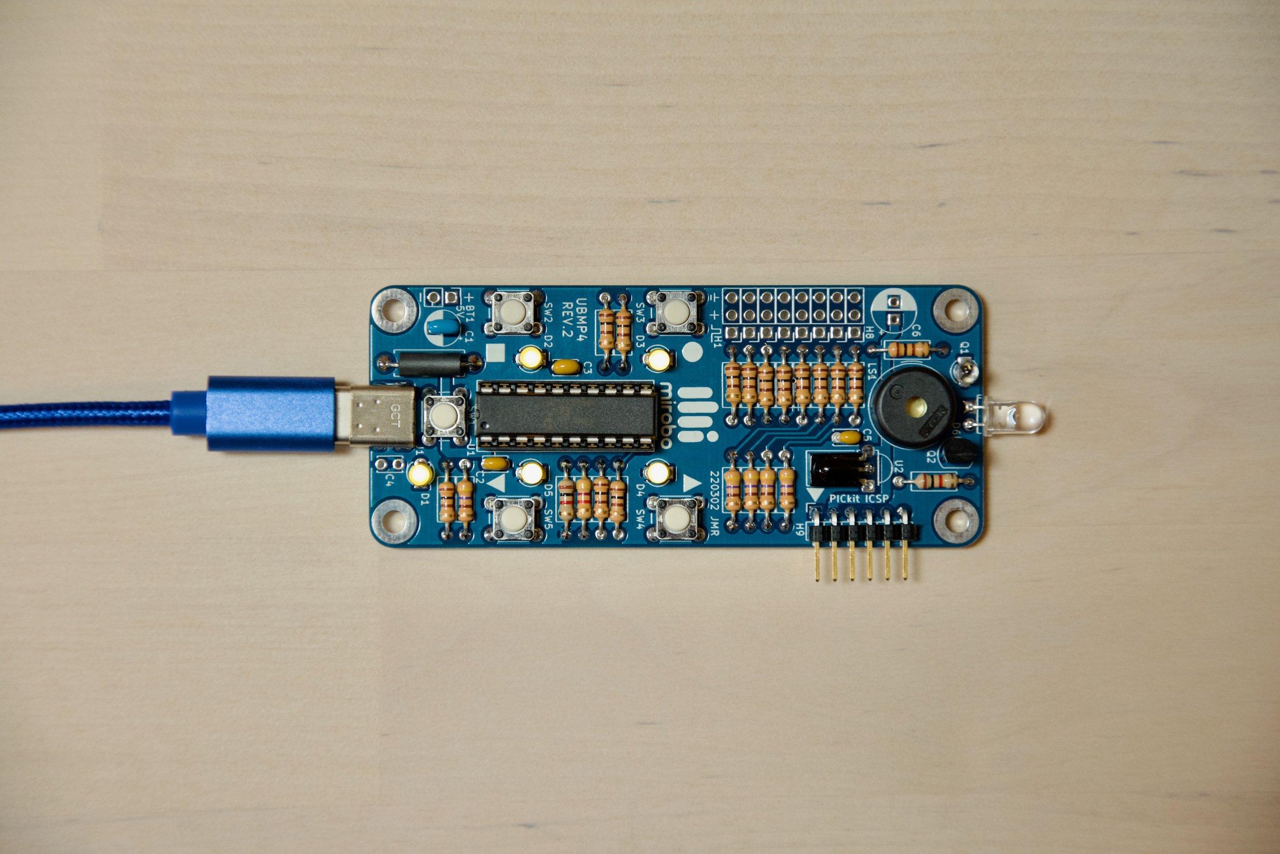
Download the Intro-2-Variables program files (.zip) to create the MPLAB project for this activity, or import the files into MPLAB from its Github repository. The contents of the main file, Intro-2-Variables.c, is shown below.
/*==============================================================================
 Project: Intro-2-Variables             Activity: mirobo.tech/ubmp4-intro-2
 Date:    May 9, 2023

 This introductory programming activity for the mirobo.tech UBMP4 demonstrates
 the use of byte (char) constants and variables to count button presses and to
 then trigger actions when a limit is reached.

 Additional program analysis and programming activities demonstrate the use of
 bit (Boolean, or bool) variables to store state for preventing multiple counts
 of the same button being pressed during successive program loops. Additional
 activities include the creation of a two-player rapid-clicker game, simulation
 of a real-world toggle button and multi-function button, and writing code to
 measure and deal with switch contact bounce.
==============================================================================*/

#include    "xc.h"              // Microchip XC8 compiler include file
#include    "stdint.h"          // Include integer definitions
#include    "stdbool.h"         // Include Boolean (true/false) definitions

#include    "UBMP420.h"         // Include UBMP4.2 constants and functions

// TODO Set linker ROM ranges to 'default,-0-7FF' under "Memory model" pull-down.
// TODO Set linker code offset to '800' under "Additional options" pull-down.

// Program constant definitions
const unsigned char maxCount = 50;

// Program variable definitions
unsigned char SW2Count = 0;
bool SW2Pressed = false;

int main(void)
{
    // Configure oscillator and I/O ports. These functions run once at start-up.
    OSC_config();               // Configure internal oscillator for 48 MHz
    UBMP4_config();             // Configure on-board UBMP4 I/O devices

    // Code in this while loop runs repeatedly.
    while(1)
	{
        // Count SW2 button presses
        if(SW2 == 0)
        {
            LED2 = 1;
            SW2Count = SW2Count + 1;
        }
        else
        {
            LED2 = 0;
        }

        if(SW2Count >= maxCount)
        {
            LED3 = 1;
        }

        // Reset count and turn off LED D3
        if(SW3 == 0)
        {
            LED3 = 0;
            SW2Count = 0;
        }

        // Add a short delay to the main while loop.
        __delay_ms(10);

        // Activate bootloader if SW1 is pressed.
        if(SW1 == 0)
        {
            RESET();
        }
    }
}
Program Operation
The top of the program contains declaration statements used to define the names, types, and values of global constants and variables:
// Program constant definitions
const unsigned char maxCount = 50;

// Program variable definitions
unsigned char SW2Count = 0;
bool SW2Pressed = false;
Each declaration statement begins with the numeric type: const unsigned char for an 8-bit constant, unsigned char for an 8-bit variable, and bool for a single-bit variable.
The the name of the constant or variable follows the type declaration: maxCount, SW2Count, and SW2Pressed. The names are in what is known as camel-case format. Camel-case names usually begin with lower case, and each successive word is joined with a capital letter, as in the constant name maxCount. The SW2Count variable keeps the capitalization of the SW2 button label. In general, it helps programmers to use descriptive names because the names provide useful context for how the constant or variable will be used. For example, even though they could be used in the exact same way, the statement maxCount = 50 is more helpful to anyone reading the code than m = 50.
The last part of a declaration is assigning a value to each constant or variable using an equal sign. Values have to be assigned to constants, and are optional for variables.
Every variable is assigned one or more locations (depending on its numeric type) in the microcontroller’s RAM. If no value is assigned to a variable during declaration, a memory location is still reserved for it in RAM, but may be left uninitialized by the compiler. This means that, as a programmer, you shouldn’t assume you know the value until after you write a value into it.
The main while( ) loop (is not what you think it is)
Following the constant and variable declarations in the program code, the main( ) function and its while( ) loop are very similar to the same sections in the Intro-1-Input-Ouput program. The big difference is the addition of multiple if-conditions within the while( ) loop, with one checking SW2 to increment the count, another checking SW3 to clear the count, and one more to check if the maximum count has been reached. There is also a delay – which doesn’t immediately seem to do anything – and the SW1 check for the bootloader at the bottom of the program.
What is this program meant to do? If you look over the code, it looks simple enough – it looks like it will count SW2 button presses and light an LED once the number of pressed exceeds a certain value.
Fair warning: this is a poorly-written program that will (probably) not work as you expected. It is meant to serve as an example of how microcontrollers expect programmers to think differently about input devices, and to help you develop an understanding of how those differences can result in some unusual behaviour. Let’s look at each part of the code to try to figure it out:
        // Count SW2 button presses
        if(SW2 == 0)
        {
            LED2 = 1;
            SW2Count = SW2Count + 1;
        }
        else
        {
            LED2 = 0;
        }
This first if-else structure lights LED2 when pushbutton SW2 is pressed (its input pin is low, or logic 0), and also increments the SW2Count variable by one each time the condition is true. If SW2 is released (its pin is high, or logic 1), LED2 is turned off. This part seems fairly straightforward.
        if(SW2Count >= maxCount)
        {
            LED3 = 1;
        }
The next if-structure compares the SW2Count variable to the maxCount constant. If SW2Count is greater or equal to maxCount, LED3 is turned on. This is a very simple structure, though it is important to realize that LED3 will stay on once the conditions is true since there is no code here to turn LED3 off. But, turning LED3 off would actually be a useful feature to have, so there is this next part that does just that.
       // Reset count and turn off LED D3
        if(SW3 == 0)
        {
            LED3 = 0;
            SW2Count = 0;
        }
The third if-structure both turns off LED3 and resets the SW2Count variable to zero if SW3 is pressed. Again, nothing seemingly unusual here.
        // Add a short delay to the main while loop.
        __delay_ms(10);
Following the if-structures we find this lone 10 millisecond delay. Unlike the delays between the light patterns in the Intro-1-Input-Output program, this one just seems to waste time in the while( ) loop. And, that is exactly its purpose – to add a bit of delay and to limit the rate at which the contents of the while( ) loop run to only 100 times per second.
Ok, the program seems simple enough. So, why the warning above that it won’t work? Build the program in your IDE, download the .hex file into the microcontroller, and see if you can figure out what it’s doing.
Learn more – program analysis activities
Did you run it? This program should light LED D2 every time SW2 is pressed, and light LED D3 once the count reaches 50. Switch SW3 resets the count so you can perform repeated attempts. Try it, and count how many times you pressed SW2 before LED D3 turned on.
Did your count reach 50? Can you describe what the program is doing? (Hint: try pressing and releasing the button at different rates of speed.)
Debugging using LEDs
If you have figured out what the program is doing yet, and especially if you haven’t, we can use the LEDs to assist us in understanding and debugging the code. Modify the second 'if' structure to add the else block, shown below. This will force LED D3 off whenever SW2Count is less than maxCount.
        if(SW2Count >= maxCount)
        {
            LED3 = 1;
        }
        else
        {
            LED3 = 0;
        }
Now, press and hold pushbutton SW2 for at least 10 seconds while watching LED D3. Did it stay stay off? Did it stay on? Did it blink on and off?
LED D3 will stay off while the value of SW2Count is less than maxCount. Similarly, LED D3 will stay on while the value of SW2Count is higher than maxCount. If LED D4 is turning on and off, what can we infer about the value of the SW2Count variable? It must be going above and below maxCount! But how could this be? There is only code in program to increase the value of the SW2Count variable, and no code to decrease it.
There is a limit to how high we can go
The variable SW2Count was defined as an unsigned char near the top of the program. Referring back to the numeric types chart, back up near the top of this page, we can see that unsigned characters can range between the values 0 and 255. As the variable counts up it will eventually reach 255 – the maximum value that an 8-bit character can contain. After reaching 255, the next increment to that variable should bump its value to 256. Since 256 is the 9-bit binary number 100000000, and since SW2Count is stored as an 8-bit variable, only the lowest 8 bits are kept in RAM – so 256 becomes the binary number 00000000, or zero. This is known as an overflow, and effectively resets the count. Each cycle of the program that the count is zero (or less than maxCount), the else statement in the comparison will cause LED D3 to turn off.
Overflow errors are common in programs, but there are simple solutions to prevent them. To avoid overflowing the count, we can set a limit on the SW2Count variable by encapsulating its increment statement inside a conditional statement.
In your program, replace the single line SW2Count = SW2Count + 1; statement with the code block shown below:
            if(SW2Count < 255)
            {
                SW2Count += 1;
            }
This code demonstrates the use of an assignment operator += to shorten the previous statement: SW2Count = SW2Count + 1;
SW2Count += 1; performs the same action of adding 1 to the current SW2Count, just in a more compact form. More importantly, adding this if-condition will only allow SW2Count to be incremented up to 255. Once SW2Count is equal to 255 the condition will be false, skipping the assignment operation, and holding the count at 255.
Current state, not change of state
With the above fix added to the program, pressing and holding pushbutton SW2 will light LED D3 after maxCount has been reached, and will keep LED D3 on because SW2Count is prevented from resetting to zero. But, why does holding the button down still allow the count to increase? Shouldn’t the program count each SW2 press? That was the goal. Let’s explore why that is not happening, and what is happening instead.
The key to understanding this program (and most microcontroller programs) is that the program is not event-based. This means that the program does not wait for pushbutton SW2 to be pressed, but rather senses SW2’s state during every cycle of the main while( ) loop.
So, if pushbutton SW2 happens to be pressed when the while loop gets to that if-section, another count will be added to the SW2Count variable. If this happens every time through the loop, SW2Count will exceed maxCount simply by holding the button for the duration of the number of loops required, because the if-condition is true each time through the program while loop. Running at a hundred loops per second – due to the 10ms delay in each loop – it will only take half of a second to exceed a maxCount of 50.
To fix it, the program needs to be made to respond only to each new press – in other words, a change of SW2 state – instead of just detecting the currently pressed state. This can be done by monitoring the change of SW2’s state from not-pressed to pressed. Doing so requires the use of another variable to store the prior state of SW2, so that its current state can be evaluated as being the same or different from its state in the previous loop. Since this variable needs to only store one of two values, pressed or not pressed, a Boolean variable can be used. The Boolean variable SW2Pressed has been defined exactly for this purpose at the top of the program.
Replace the initial SW2 if-else condition in your program with the following block of two if conditions:
        // Count new SW2 button presses
        if(SW2 == 0 && SW2Pressed == false)
        {
            LED2 = 1;
            SW2Pressed = true;
            if(SW2Count < 255)
            {
                SW2Count = SW2Count + 1;
            }
        }

        // Clear pressed state if released
        if(SW2 == 1)
        {
            LED2 = 0;
            SW2Pressed = false;
        }
These two if conditions use the Boolean SW2Pressed variable to remember the state of SW2 for the next cycle of the main while loop. Boolean variables can store the values 0 or 1, which the compiler interchangeably represents as false or true, respectively.
The first if condition compares the current SW2 state with the previously stored SW2Pressed variable, and only allows a new count be added when button SW2 is pressed and – using the logical AND condition operator, && – the Boolean SW2Pressed variable is false. If SW2 is pressed, the SW2Pressed variable is set to true in this first if-structure. This prevents the contents of this same if-structure from running the next time through the program loop, since the AND condition in the if-statement requires SW2Pressed to be false.
The second if-structure, above, resets the SW2Pressed Boolean to false whenever the button is released, allowing the next new press of SW2 to enter the first if-structure again.
Try the code to make sure it works as expected. Pressing and holding SW2 should no longer increase the count, and you will now have to repeatedly press and release SW2 to turn LED D3 on.
Logical NOT
The conditional statement in the first if condition can also be written with the logical NOT operator – typed as ! (an exclamation mark):
if(SW2 == 0 && !SW2Pressed)
Read the !SW2Pressed expression as 'not SW2Pressed' – it is the equivalent of variable SW2Pressed being false. Conversely, if we used the SW2Pressed variable name by itself in a condition – without an exclamation mark – it would be the equivalent of being true.
Defined states
Any variable’s state can be defined as a word or constant to make the code more readable. Add the following definitions to the Program constant definitions section at the top of the code:
#define pressed 0
#define notPressed 1
Now, instead of comparing the state of the button to 0 or 1, the button input can be compared to the named definitions representing 0 or 1, which makes the program more readable, though at the expense of hiding the actual switch value in the definition statement. Try it in your code. You can also modify the SW3 reset button to work the same way.
        // Count new SW2 button presses
        if(SW2 == pressed && SW2Pressed == false)
        {
            LED2 = 1;
            SW2Pressed = true;
            if(SW2Count < 255)
            {
                SW2Count = SW2Count + 1;
            }
        }

        // Clear pressed state if released
        if(SW2 == notPressed)
        {
            LED2 = 0;
            SW2Pressed = false;
        }
Activity 2 learning summary
Program variables can represent different sizes and types of numbers. It is an important programming requirement to specify the type of each variable, and good practice to select the best numeric type to represent each variable’s range of values. In a small, relatively low performance microcontroller like the PIC16F1459, selecting the smallest variable types can both reduce memory requirements and improve processor performance.
Since most microcontroller programs run their code as part of a main loop, statements that check the state of inputs run repeatedly, making them unsuitable to count individual input events. To detect a change in input, use a variable to remember an input state from loop to loop, and count new events only when the state changes.
Binary numbers can overflow and underflow their bit sizes when incremented or decremented, creating unexpected results. For this reason it is very important to implement bounds checking to prevent numeric variables from going out of their safe ranges.
While the I/O circuitry of a board such as the UBMP4 is very limited, LEDs can be a simple tool for debugging purposes by adding code to your program that turns them on or off when specific values have been reached, or when certain parts of a program are run.
Programming Activity 2 Challenges
1. Can you make a two-player rapid-clicker style game using this program as a starting point? Use SW5 for the second player's pushbutton so that the two players can face each other from across the CHRP4 circuit board. Duplicate the SW2Count and SW2Pressed variables to create SW5Count and SW5Pressed variables. Then, duplicate the if condition structures to modify the variable names to represent the second player. LED D3 can still light if player 1 is the first to reach maxCount and wins. Use LED D4 to indicate when player 2 wins. Use a logical condition statement to reset the game by clearing both players' counts as well as turning off the LEDs if either SW3 or SW4 is pressed.
2. Use your knowledge of Boolean variables and logical conditions to simulate a toggle button. Each new press of the toggle button must 'toggle' an LED to its opposite state. (Toggle buttons are commonly used as push-on, push-off power buttons in digital devices.)
3. A multi-function button can be used to enable one action when pressed, and a second or alternate action when held. A variable that counts loop cycles can be used to determine how long a button is held (exactly as the first program unitentionally did because of the loop structure). Make a multifunction button that lights one LED as soon as a button is pressed, and lights a second LED after the button is held for more that one second.
4. Do your pushbuttons bounce? Switch bounce is the term that describes switch contacts repeatedly closing and opening before settling in their final (usually closed) state. Switch bounce in a room's light switch is not a big concern, because we wouldn't notice the lights rapidly flashing before staying on. But, switch bounce is an issue in a microcontroller toggle button program because the speed of a microcontroller lets it see each bounce as a new, separate event, and make it perform multiple actions in response to one button press.
Create a program that uses a variable to count the number of times a pushbutton is pressed and to then display the count on the LEDs. Use a second pushbutton to reset the count and to turn off the LEDs so that the test can be repeated. To determine if your switches bounce, try pressing them at various rates of speed and using different amounts of force.
5. Did your pushbuttons bounce? Can you think of a technique similar to the multi-function button that could be implemented to allow your program to ignore switch bounces?
Typical switch bounces appear as multiple switch activations within a 10ms time span. So, if our program can be made to ignore any new switch activations for 20ms after the first switch closure, it should eliminate the effects of bounce. See if you can add switch de-bouncing code to your bounce counting program in 4, above.