
ARPS Introductory Programming Activity 1
This is the first of five step-by-step introductory programming activities specifically designed to help you learn the fundamentals of Arduino® programming using the mirobo ARPS circuit. Most of the concepts introduced in these activities can easily be applied to other Arduino circuits and programs, too.
After working through the first four out of five introductory activities, you should be able to confidently write programs to tackle most basic microcontroller interfacing and control tasks, and you will be ready to move on to the more advanced programming activities on this website. Let’s get you started on your programming journey!
Input and output
The first step in getting any new microcontroller circuit to do something useful is learning to create programs that read inputs, make decisions, and control output devices. This simple input and output (I/O) program does exactly that, teaching you these fundamental concepts that will be used in all of your future microcontroller programs.
Learning objectives
In this programming activity you will learn about the basic structure of Arduino programs, and how to write programs to:
read pushbutton inputs
turn individual outputs on and off
work with built-in time delay functions
combine if conditions in input statements
make logical AND and OR input conditions, and
make sounds using the beeper and the tone( ) function
Activity overview
All of the introductory programming activities will follow the same format, and have been designed to help you learn by doing. The activities follow a format that can be described using the acronym RAMP-M, incorporating each of the following steps:
Run the provided example program to see what it does.
Analyze the program and its operation to learn new concepts.
Modify the program to extend existing ideas and to introduce new or related concepts.
Predict, test, and analyze the results of the modifications to build deeper understanding.
Make new programs by applying the concepts learned in new or different ways.
Every programming activity starts with an example programming project that you can copy from the activity or download from GitHub, paste into your IDE, and upload into your circuit for testing.
Next, program analysis activities (also found in the program source code) will introduce new learning and guide you through the exploration of related concepts to help you develop a better understanding of the program and its operation. You will do this by making small modifications to the existing program and predicting and testing the outcomes after these changes.
Finally, programming challenges at the end of the activity (and also in the program source code) give you the opportunity to practice and extend your new software and hardware skills. The programming challenges are designed to give you the confidence to tackle new and different programming tasks while building and expanding on the same basic concepts introduced in the activity.
Getting started
To complete these activities you will need:
A computer running the Arduino IDE or Arduino Web Editor, both of which are available from the Arduino Software page of the Arduino.cc website, or an Arduino circuit simulator such as Tinkercad.
a) An ARPS circuit that is either fully assembled, or an ARPS circuit assembled with the minimal set of components in the Educational Starter configuration, plus an Arduino UNO R3 or Arduino UNO R4 circuit to plug ARPS into, and the appropriate USB 2.0 cable to connect the Arduino to your computer. Or,
b) An Arduino simulator with the components used in the ARPS Education Starter configuration connected to the same I/O pins as in the ARPS circuit, as available in this Tinkercad ARPS activity 1 simulation.
ARPS is designed to work best with the new Arduino UNO R4 Minima. Due to its limited and shared I/O pins, Arduino UNO R3 is not able to use ARPS pushbuttons SW2 and SW3 when it is programmed through USB.
New Concepts
You might be new to Arduino, or new to programming in general – don’t worry, we’ll take it step-by-step. Here are some important terms and other things you should know to get started:
Arduino programs a written in a C++ language syntax and are commonly known as sketches. They can be created in the Arduino IDE (available from arduino.cc) and in other circuit simulation tools such as Tinkercad.
most Arduino programs are written in single source code file (ending with a .ino file extension), and can include other header files (ending with .h file extensions) that can be used to add additional functionality to the programs.
every Arduino program has to include both a setup( ) function and a loop( ) function.
program statements are grouped inside each function’s opening and closing curly braces { }, as shown below:
void setup() {
  pinMode(onboardLED,OUTPUT);
  ..
}
blocks of program statements making up structures such as if conditions or for loops are also grouped inside curly braces – { }
individual statements or expressions are terminated by a semicolon ( ; ) – think of a semicolon as being similar to a period at the end of a sentence.
statements inside curly braces are indented for readability, but the type and amount of spacing used for indenting doesn’t matter to the compiler – consistent spacing just makes the code easier for users to read and debug.
single-line code comments are ignored by the compiler and start with double slashes – //
multi-line code comments start with /* and end with */
Step 1 - Download the Activity 1 sketch
Download the ARPS Activity 1 sketch from its GitHub repository, and open it in your Arduino IDE. The ARPS Activity 1 source code in GitHub includes additional program analysis and programming activities in the comments at the bottom of the program. If these are not needed, you can simply copy and paste the ARPS Activity 1 program listing, below, into your Arduino IDE.
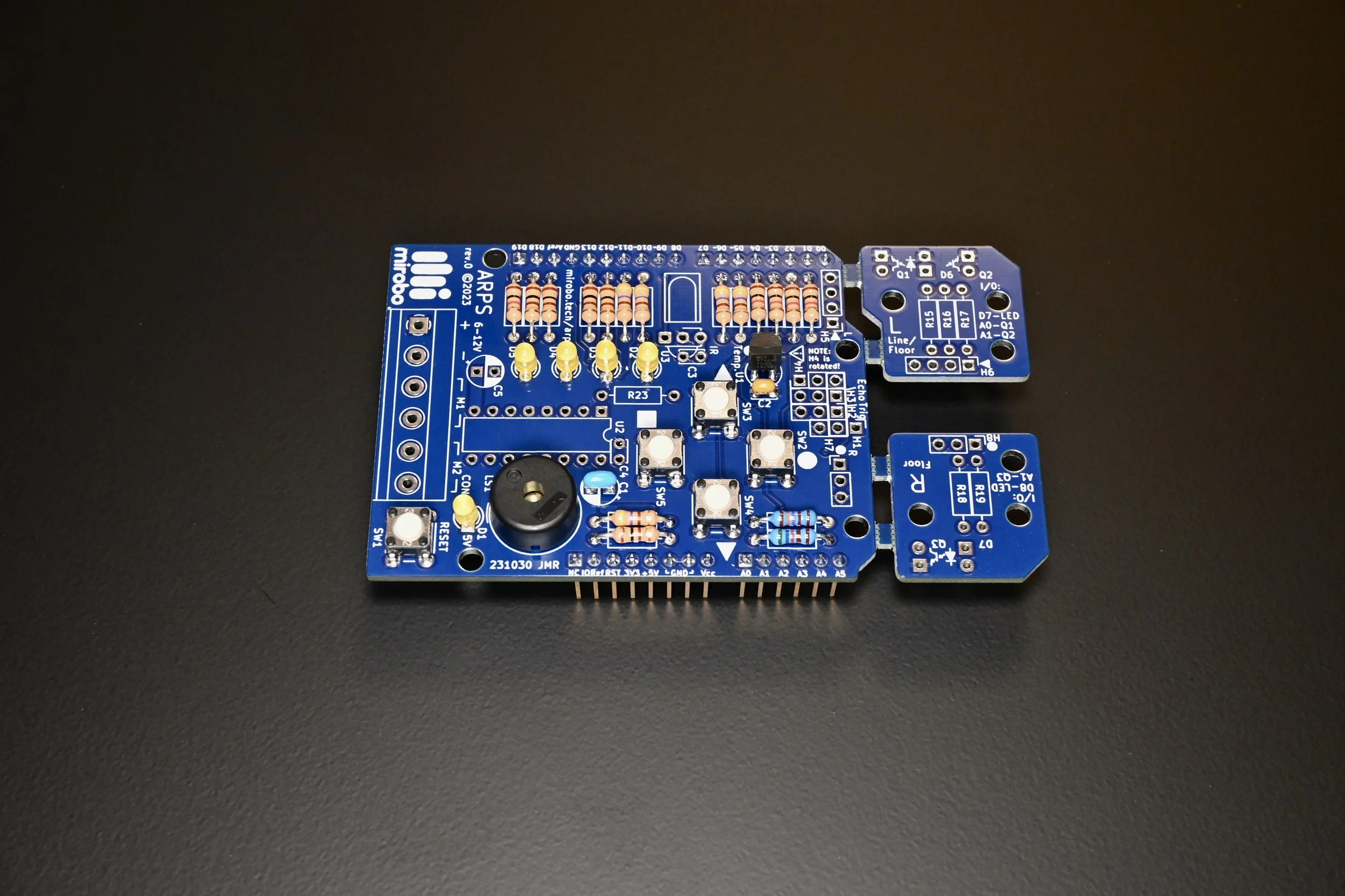
Step 2 - Connect ARPS to Arduino
Connect ARPS to your Arduino UNO by carefully aligning its bottom-mounted header pins with the upward-facing header sockets on Arduino UNO, and gently press ARPS into place.
Important! Inspect the area above the USB connector on the Arduino UNO R3 to ensure that the metal shell of the USB connector is not shorting the pins of the screw terminal strip on ARPS. If the solder leads of the screw terminal strip are making contact with the metal casing of the USB connector, cut the solder leads as short as possible and add a strip of insulating tape across the bottom of the ARPS screw terminal strip to insulate its leads from the USB connector. Arduino UNO R4’s lower-profile USB type-C socket is far enough away from the screw terminal strip that it will not have the same problem.
After ensuring that the Arduino and ARPS components do not make contact, connect the Arduino to your computer using an appropriate USB cable.
Step 3 - Upload the program into Arduino
Compile the ARPS Activity 1 program and upload it into your Arduino using the Upload button in the Arduino IDE. After the program is successfully uploaded, you should hear a short beep. Then, try pressing the SW2 pushbutton on ARPS to see the LEDs flash in a pattern!

Important! Ensure there is a gap between the Arduino UNO R3 USB connector shell and the leads of the ARPS screw terminal strip.
Program analysis
If you are new to programming, or just new to C/C++ programming, there are a lot of new concepts that will be introduced in the next few sections. First, we will explore contents and structure of the program’s source code, especially the setup( ) and loop( ) functions. Next, we will analyze how the program reads the pushbuttons and lights the LEDs to make a flashing light pattern. Finally, we will expand our learning by experimenting with conditional and logical operations.
The Activity 1 program
/*
 Project:  Intro-1-Input-Output        Activity: mirobo.tech/arps-intro-1
 Date:     January 12, 2024

 This introductory programming activity for the mirobo.tech ARPS circuit
 demonstrates pushbutton input, LED outut, the use of time delay functions,
 and simple 'if' condition structures.

 Additional program analysis and programming activities demonstrate logical
 AND and OR conditional operators, the tone() function to create sound, and
 software-based simulated start-stop button functionality.
*/

// Define I/O pins used for human interface devices
const int SW2 = 0;      // ARPS pushbuttons SW2 and SW3 are supported on
const int SW3 = 1;      // Arduino UNO R4 Minima and Arduino UNO R4 WiFi
const int SW4 = 2;      // ARPS pushbuttons SW4 and SW5 work on all
const int SW5 = 3;      // Arduino UNO R3 and Arduino UNO R4 circuit boards

const int LED2 = 5;     // ARPS top-side LEDs
const int LED3 = 6;
const int LED4 = 9;
const int LED5 = 10;

const int BEEPER = 11;  // ARPS Piezo beeper LS1

const int onboardLED = 13;  // Arduino on-board LED

// Define variables
int SW2state;
int SW3state;
int SW4state;
int SW5state;

// Setup code runs once to configure I/O pins before running main loop
void setup() {
  pinMode(onboardLED,OUTPUT);
  pinMode(SW2,INPUT_PULLUP);
  pinMode(SW3,INPUT_PULLUP);
  pinMode(SW4,INPUT_PULLUP);
  pinMode(SW5,INPUT_PULLUP);
  pinMode(LED2,OUTPUT);
  pinMode(LED3,OUTPUT);
  pinMode(LED4,OUTPUT);
  pinMode(LED5,OUTPUT);
  pinMode(BEEPER,OUTPUT);
  tone(BEEPER,4000,100);  // Say hello!
}

// Main loop code repeats forever
void loop() {
  SW2state = digitalRead(SW2);  // Change to SW4 or SW5 for Arduino UNO R3

  if(SW2state == LOW) {
    digitalWrite(LED2,HIGH);
    delay(100);
    digitalWrite(LED3,HIGH);
    delay(100);
    digitalWrite(LED4,HIGH);
    delay(100);
    digitalWrite(LED5,HIGH);
    delay(100);

    digitalWrite(LED2,LOW);
    delay(100);
    digitalWrite(LED3,LOW);
    delay(100);
    digitalWrite(LED4,LOW);
    delay(100);
    digitalWrite(LED5,LOW);
    delay(100);
  }

  // Add your Program Analysis Activities and Programming Activities code here:

  delay(10);  // Added delay helps simulators run this program
}
Can you identify the two different types of comments used in this program? It contains both a comment block as well as single line comments.
The program header
The top part of most programs includes a section referred to as the program header. Program headers typically contain comments, optional include statements, and various constant and variable declarations that are important for the program’s operation.
The top-most part of this program’s header starts with a multi-line comment block enclosed within /* and */ characters. Other parts of the program include two other varieties of single line comments that follow double slash // characters and either comment out an entire line of code, or just the ending part of the line following the // characters. Comments can be used to document programs in general or to explain parts of the program code, and the contents of both comment blocks and comment lines are ignored by the compiler.
Following the program’s introductory comments are the I/O definitions and variable declarations. An excerpt of the program header shows some of these definitions, below:
// Define I/O pins used for human interface devices
const int SW2 = 0;      // ARPS pushbuttons SW2 and SW3 are supported on
const int SW3 = 1;      // Arduino UNO R4 Minima and Arduino UNO R4 WiFi
const int SW4 = 2;      // ARPS pushbuttons SW4 and SW5 work on all
const int SW5 = 3;      // Arduino UNO R3 and Arduino UNO R4 circuit boards

const int LED2 = 5;     // ARPS top-side LEDs
const int LED3 = 6;
..
..

// Define variables
int SW2state;
int SW3state;
int SW4state;
int SW5state;
I/O pin definitions
I/O pin definitions make it easier for users to program a circuit by providing each I/O device with a more meaningful name than the numeric address of the I/O port pin that it is connected to. For example, the I/O definition allows a user to control component LED D2 on the ARPS circuit using its newly-defined name, LED2, instead of needing to refer to the schematic diagram or try to remember that LED D2 is connected to the Arduino’s digital I/O pin D5.
Arduino I/O definitions both define and name the constants, and then assign each constant a value using a compact C++ statement format. For example, the the first definition statement const int SW2 = 0; declares that it is defining a constant, that the constant will be represented by a type of number known as an integer, that the constant should be assigned the name SW2, and that the constant will represent the value of 0. Any time that the compiler encounters the name SW2 in the program code that follows the definition, it can substitute the constant SW2 with its known value of 0.
An interesting aspect these I/O pin declarations is that although they form a part of the program’s source code, they don't actually become a part of the final program run by the microcontroller. The definitions simply provide information that will be used by the compiler as it compiles the program into the machine code program that will run in the Arduino’s microcontroller. This is both interesting and useful to know as it helps to provide a better understanding of how the C++ language and its compilation process works. Notably, C++ program source code contains both statements that will become instructions for the microcontroller, as well as definitions, directives, and other useful information just for the compiler, including I/O definitions like these that are mostly helpful for us, the human programmers!
Variable declarations
Four variable declarations are located below the I/O pin definitions, and you have probably already noticed that they have a very similar structure to the previous I/O pin definitions. The first one, int SW2state;, creates a variable named SW2state which is designed to hold a number from a family of numbers that are expected to be a type of integer. We will learn more about different numeric types in the next activity, but for now all you need to know is that the numeric type int is the most common type of number used in Arduino programs, and that an int number can have any value in the range between -32 768 and 32 767 (in the Arduino Uno R3 at least – Arduino Uno R4 uses 32-bit integers instead of 16-bit integers, and these allow for a larger range of possible numbers).
Note that in this case the variable SW2state is not assigned an actual value, but it could have been assigned a value by appending the line with an equal sign and a number – exactly as was done with the I/O pin definitions. For example, the statement int SW2state = 1; would have created the SW2state variable and stored the value 1 in it.
When a variable is declared, the compiler assigns the variable’s name to the internal memory address of a memory register inside the microcontroller. The register’s address will not change as the program runs, but the contents of the memory register are able to be changed by any part of the program that uses the variable.
Image this being like a labelled bookshelf in your room – let’s call it myShelf. You can put anything you want on myShelf, as long as it fits (that’s the type part, from above), and you can change what you put on myShelf at any time (and so could anyone else that enters your room. Right now your bookshelf might be holding a book, but later you might remove the book and set your Arduino and ARPS circuit there instead. Unlike a real bookshelf, which might have room to hold a number of books and an Arduino circuit at the same time, a memory register used for a variable can only hold one thing (in this case a number) at a time.
Again, just as with the I/O pin definitions, assigning meaningful names to variables in a program makes it much easier for human programmers to use the variables instead of having to remember the numeric address of internal microcontroller registers. (If you know any really old programmers, they may have had experience doing exactly this while writing early computer programs in assembly code.) As with I/O pin definitions, these variable definitions are directives that are primarily used by the compiler to help you program your microcontroller.
Arduino functions and program structure
Functions are blocks of program statements that, taken together, perform a specific task. Functions are declared using function definition statements (these include the type of data that can be optionally returned by the function, the function’s name, and optional parameters that can be provided to a function – and we will learn much more about exactly how to create and use our own functions in a later activity).
For now, it’s very important for you to know that every Arduino program must contain both a setup( ) function and a loop( ) function, and that any other functions are optional. These two functions have distinct characteristics and essentially divide every program into two parts. The first function, as you might have guessed, includes statements that set up important parts of the program before it can get to its main control tasks, such as configuring I/O pins and pre-loading variables. The setup function of a program only runs once.
The second part of the program is a loop, implying that the all of the statements inside the loop function will run repeatedly. But why would a microcontroller program need to be set up this way? If you think about the kinds of tasks that microcontrollers usually do, it makes perfect sense.
Microcontrollers typically control devices or processes that generally do a single thing, and just keep doing whatever the thing is that they were designed to do. The microcontroller running inside a television remote control, for example, only ever needs to run the program that makes it operate as a remote control. After its batteries are installed, the television remote control’s program starts up by running something equivalent to our setup function, to prepare the microcontroller in the remote to use the buttons and infrared (IR) LED. After the I/O pins have been configured and set up, the television remote just needs to repeatedly check for a button press and transmit a coded signal to the television set whenever a button is pressed. After the button is released, it just waits for the next button press which will repeat the process again. Wait for a button press, send a code – forever. Or, at least until the batteries die or are removed from the remote!
This type of program structure – a small configuration section followed by an infinite loop – is the most common way that simple microcontroller programs end up being designed and structured because it is a simple and logical way to control a device or process. Now that we have a better understanding of the structure of this program, let’s dive into the details of how this introductory program works.
The setup( ) function
The setup( ) function contains the very first statements of the program to be run by the microcontroller, and all of the statements in the setup( ) function run just once.
// Setup code runs once to configure I/O pins before running main loop
void setup() {
  pinMode(onboardLED,OUTPUT);
  pinMode(SW2,INPUT_PULLUP);
  pinMode(SW3,INPUT_PULLUP);
  pinMode(SW4,INPUT_PULLUP);
  pinMode(SW5,INPUT_PULLUP);
  pinMode(LED2,OUTPUT);
  pinMode(LED3,OUTPUT);
  pinMode(LED4,OUTPUT);
  pinMode(LED5,OUTPUT);
  pinMode(BEEPER,OUTPUT);
  tone(BEEPER,4000,100);  // Say hello!
}
The setup function starts with the function declaration void setup( ), which compactly describes the function as a stand-alone function that doesn’t provide any data (void), is named setup, and which does not require any other data – the empty brackets ( ) – to do its job.
The setup function contains all of the program statements within the set of curly braces { } that follow the function declaration in the program code – from the top opening brace { right beside the void setup( ) declaration, to the bottom closing brace }, aligned with the left margin at the end of the function. Sets of braces group all of the program code within them together, and the spacing of the braces from the left margin shows the code hierarchy. So, in this program, the setup function contains just the lines of code that are indented below it.
What does this setup code do? Most of the statements in the setup function are pinMode function statements that configure the direction of each of the Arduino I/O pins that will be used by this program. Direction in this case refers to whether a pin is an INPUT pin, including the special INPUT_PULLUP type specified here, or an OUTPUT pin, where the terms input and output are defined from the perspective of the microcontroller on the Arduino board. Every I/O pin that will be used by a program must be configured before use, and most of the pin functions won’t need to change while the program runs, so the setup function is an ideal place to put the configuration instructions and to configure the I/O pins before the main part of the program runs.
The last setup statement is a tone function that plays a short beep through the speaker to let you know that the Arduino and its attached ARPS circuit are active.
The loop( ) function
The loop( ) function begins with the function declaration void loop( ), located just below the setup function, and includes all of the program statements within its set of curly braces { }, as shown below:
// Main loop code repeats forever
void loop() {
  SW2state = digitalRead(SW2);  // Change to SW4 or SW5 for Arduino UNO R3

  if(SW2state == LOW) {
    digitalWrite(LED2,HIGH);
    delay(100);
    digitalWrite(LED3,HIGH);
    delay(100);
    digitalWrite(LED4,HIGH);
    delay(100);
    digitalWrite(LED5,HIGH);
    delay(100);

    digitalWrite(LED2,LOW);
    delay(100);
    digitalWrite(LED3,LOW);
    delay(100);
    digitalWrite(LED4,LOW);
    delay(100);
    digitalWrite(LED5,LOW);
    delay(100);
  }

  // Add your Program Analysis Activities and Programming Activities code here:

  delay(10);  // Added delay helps simulators run this program
}
The setup function consists of all of the code inside of the opening { and closing } braces. The program code inside the setup function is indented to show the reader that it belongs to, and is a part of, the setup function. Most Arduino IDEs will automatically help to consistently indent your program code.
Checking for a button press
The loop is essentially split into three sections, and the first two sections work together to check for a button press. It starts with the first statement which assigns variable SW2state the level of the pushbutton input after the digitalRead(SW2); function measures it, and then the next if condition statement checks the resulting variable to determine if SW2 is pressed or not:
void loop() {
  SW2state = digitalRead(SW2);

  if(SW2state == LOW) {
    digitalWrite(LED2,HIGH);
    delay(100);
    ..
    ..
If SW2 is pressed…
How does the Arduino know if SW2 is pressed? The digitalRead function will return one of two values based on the voltage measured on its selected I/O pin; either LOW if the voltage on the SW2 pin is below approximately 1V, or HIGH if the voltage is higher than approximately 2V (although the actual voltages vary based on the particular microcontroller in the Arduino circuit being used). The values LOW and HIGH are defined as constants by the Arduino IDE, and have to be spelled in ALL CAPS, just as shown here, or the IDE will produce an error when the program is compiled.
An if condition then compares the value stored in the SW2state variable with the LOW constant. Comparing two values for equality in C++ is always performed using a double equal sign == , and this is also the case in many other programming languages.
The reason SW2 is checked for a value of LOW is that the switch circuits on ARPS are wired to take advantage of the built-in pull-up resistors in Arduino. When a switch is not pressed, the pull-up resistor will cause the Arduino microcontroller pins to be ‘pulled-up’ to the 5 V power supply level and read as a high voltage, or HIGH level. When the switches are pressed, the microcontroller pins are connected to ground and are read as a low voltage, or LOW level.
So, if pushbutton SW2 is pressed, the SW2state variable will be LOW making the if conditional statement true, and each of the program statements inside the if structure’s braces will run in sequence – once.
The first statement uses a digitalWrite function to turn LED2 on by writing a HIGH to its output pin, causing the Arduino circuit to output a 5V level on pin 5, the pin defined earlier in the programs as being equivalent to LED2. This 5V level causes current to flow through LED D2’s series resistor as well as through LED D2, turning it on.
Next, the delay(100); statement is a built-in compiler function to produce a 100 ms (or 0.1 s) time delay that keeps LED D2 lit for this period of time and prevents anything else in the program from happening for 100 ms. The rest of the digitalWrite and delay commands that follow these first two statements are executed in sequence, turning each of the LEDs on and then off, with a delay added between each step, until the program reaches the closing curly brace of the if structure. At this point the execution of the if structure is complete, and the program continues to the next statement below its closing brace.
What if SW2 is not pressed?
If SW2 is not pressed the pushbutton’s state would be HIGH, making the if condition false, and causing all of the code inside the if structure’s curly braces to be bypassed. The program would simply continue to the next statement, located below the closing brace of the if structure, and get to the single line of code that follows:
delay(10); // Added delay helps simulators run this program
This short delay is not entirely necessary, but adding a delay into the loop function can serve a few purposes. The comment gives a clue about one purpose of the delay – it reduces the number of times the program loop runs every second making it easier for some software-based Arduino simulators to run the program.
Another thing that a loop delay can do is to make programs that use on switch input potentially more reliable by using the delay as a form of switch debouncing (we’ll learn more about that in Activity 2). A de-bounce delay is not needed here, given the nature of the long delays in the LED flashing pattern when a switch is pressed, but it can work well in programs that perform very quick actions after a switch is pressed.
Won’t adding a delay make the program run more slowly? Yes, but that won’t matter at all for this program. Instead of being able to potentially sense the state of pushbutton SW2 thousands of times per second, the delay limits the program to sensing SW2 just one hundred times per second – that’s still much faster than all of the humans I hang out with!
Finishing the main loop
Whether SW2 was pressed or not, after running the delay(10); statement the microcontroller has reached the end of the program in the main loop( ) function. Since the Arduino loop( ) function is an infinite loop, program execution will automatically resume from the beginning of the loop, repeating the same button input, if condition check, and short delay, forever. Pushbutton SW2 will be checked every loop, and the program will make a pretty flashing pattern whenever SW2 is pressed, until power is either removed from the circuit or the circuit is re-programmed with a different program.
Learn more – Program analysis activities
Hooray, if you made it this far you should have a basic understanding of how this program flashes LEDs in response to a button press! Next, we will modify parts of the existing program code, building on the concepts introduced earlier and helping you to further your understanding of microcontroller operation and C++ language features.
A condensed version of some of these analysis activities is embedded in the comment block below the source code in the program to make it easier for you to copy and paste the example code directly into the program from inside the Arduino IDE. Add the new program instructions at the location shown by the single line comment in the program code – it’s located right after the first if structure and before the delay(10); statement at the end of the loop function.
1. Microcontrollers can only do one thing at a time
Microcontrollers are fast, and they can only do one thing at a time – in this example at least. Hardware modules can allow microcontrollers to perform certain kinds of tasks while the software in the program is doing something else, but that capability is not being in this example. In this program, everything is accomplished through software with one instruction following another, in sequence.
Quickly press and release pushbutton SW2, once. You should see the flashing pattern light up and turn off the LEDs in sequence, once. Press and hold pushbutton SW2. You should see the flashing pattern continue while you hold the button. What do you think will happen if you press SW2 twice, really quickly, so that both button presses happen during the time it takes to do one complete flashing pattern?
If you think about how other circuits you may have come across work, you might be able to predict that the program will respond with one of these three possible outcomes:
The one thing at a time outcome. The flashing pattern will start immediately after the first button press and will continue until the flashing pattern ends after just one cycle, ignoring the second button press. The circuit will not start the flashing cycle again until SW2 is pressed agin after the first flashing cycle has ended.
The rapid-fire outcome. The flashing pattern will start immediately after the first button press, and the second button press will immediately re-start the flashing pattern. Every new press of SW2 will re-start the flashing pattern no matter where in the pattern the program happens to be.
The button memory outcome. The flashing pattern will start immediately after the first button press, complete the whole first flashing pattern, and then start a second pattern since the microcontroller remembers that SW2 was pressed twice. No matter how many times SW2 is pressed, the pattern will flash once for every button press.
Try it! Which outcome is correct? Why? It helps to understand that microcontrollers execute one instruction at a time, in order, as they work their way through a program. Using that logic, the correct outcome has to be the first one.
Here’s why. After SW2 is first pressed, the program starts to execute the instructions inside the curly braces of the SW2 if structure. While each digitalWrite instruction and delay function within the if structure is being run, the program does not check SW2 again, and will not know (or care) about the state of SW2, eliminating outcome 2, above. SW2 will only be sensed again after the first full flashing cycles ends, when the while loop is re-run. If the second button press happens while the flashing pattern is being output, there can be no memory of it. Bye-bye outcome 3. Only outcome 1 matches the program and our observation.
2. HIGH, LOW, and volts
How does the digitalWrite(LED2,HIGH); statement actually turn on LED D2? How does digitalWrite(LED2,LOW); turn LED D2 off? We could say this is the magic of software and hardware interaction, but you probably want a more technical explanation for it! It’s actually the magic of memory-mapped I/O.
Okay, magic really has nothing to do with it. Here is how it works. We know that the SW2state variable is just name given to a memory register inside the Arduino’s microcontroller chip. The digitalRead(SW2); function uses the circuitry in the microcontroller to read the voltage on one of the microcontroller’s pins, and then stores a representation of that voltage in the SW2state memory register. The microcontroller does not store the exact measurement that a voltmeter would provide (say 4.96V), because that level of accuracy is not necessary for this program to work and, importantly, the digitalRead operation simplifies the resulting voltage measurement to one of two states: a voltage above approximately 2V is stored as HIGH, and a voltage below approximately 1V is stored as LOW. (If an accurate voltage measurement is needed, the analogRead( ) operation that can be used instead – a future activity will explore that function.)
What are HIGH and LOW really? HIGH and LOW are ones and zeroes stored in the memory of the microcontroller, but like HIGH and LOW, one and zero are just terms that we use to represent particular voltage levels inside the internal memory circuits of the microcontroller. For our application, it doesn’t actually matter if HIGH is one, or zero, or 4.58V, or 0.27V, as long as it is used in a consistent way. So, in this program, we expect that if a switch input pin is HIGH, it’s level will match an LED output pin when we also make it HIGH.
When this program runs the digitalWrite(LED2,HIGH); statement, the microcontroller puts its electrical equivalent of the HIGH state into the memory circuit representing LED2’s I/O pin. The microcontroller’s I/O circuits translate the internal voltage in the memory circuit into an external voltage on a pin, and the pin associated with the LED2 constant defined in our program will now output a voltage of 5V (in a microcontroller running at 5V like the one in Arduino Uno R3, and R4, or 3.3V in the microcontrollers used in some other Arduino circuits). Because of the way that the external circuits circuits are connected, a HIGH output will turn LED2 on. Likewise, the digitalWrite(LED2,LOW); statement will output 0V to the LED2 pin, turning LED2 off.
So, memory-mapped I/O is not actually magic, but just the application of circuits that convert an external voltage to an internal voltage that is recognized as being a particular state by the software, as well as the reverse of that – software that sets a state in memory, that I/O circuits convert to a voltage on one of the external pins of the microcontroller.
3. External series circuits
Let’s examine the external series circuits that connect the ARPS LEDs to Arduino:

Each LED has its cathode (negative) pin connected to ground, and its anode (positive) pin wired to its respective Arduino digital I/O pin (D5, D6, D9, or D10) in series with a 470Ω resistor. The resistor is really important to limit the maximum current that can flow through the LED, both to protect the LED and the Arduino output circuit from excessive current flow, as each one can be damaged or destroyed if the current is too high.
This is a typical arrangement of output devices in most microcontroller circuits – output pins connect to output devices through a small series resistor. How big should the resistor be? It depends on the output device. Output devices with high input impedance such as the ICs used in the optional SONAR module for ARPS can benefit from the addition of relatively small (eg. 100Ω) resistors to control high-speed switching noise while not really affecting the output signal (these are relatively advanced electronic concepts that you might study later, but until then just remember that adding a small resistor to an output pin is a good idea to do in general).
Output devices such as LEDs use their series output resistors to set their operating current. Most visible-light LEDs should not exceed 20mA of operating current (check the data sheet for the actual maximum current, but 20mA is usually a safe value), and appear to be nearly the same brightness at one-half, or even one-quarter of their maximum current. So, reducing the LED current has the benefit of significantly improving battery life in battery-powered circuits while not visibly impacting their apparent brightness. Assuming a 5V Arduino output voltage, and a forward voltage drop of 2V across each individual LED, the resistor current can be calculated as follows:
(5V - 2V) / 470Ω = 6.38mA
In series circuits, all devices must have the same current flowing through them, and this means that the LED current will be the same as the resistor current. It’s a safe value, at about 1/3 of the maximum current for many LEDS, and they seem to be bright enough for most indoor applications.
If you have a multimeter, you can verify the voltage across both the resistor and the LED. You may need to increase the delays in the program to get an accurate reading, or use the peak hold function of your multimeter if it has one. When you take the measurement, measuring from the digital I/O pin to ground should give 5V, while measuring across the LED will give a lower voltage due to the voltage drop across the resistor which protects the LED.
4. Assignment and conditional operators
In the program, the statement SW2state = digitalRead(SW2); uses the single equal sign as an assignment operator. The value HIGH or LOW will be assigned to the SW2state variable when the statement runs.
The statement if(SW2state == LOW) uses two equal signs as a conditional operator instead of one. Why does it need to do that? It would seem that wording the conditional statement with a single equal sign would make just as much sense as using two equal signs, and using just one equal sign make life easier for programmers than having to remember to use two equal signs.
The answer to this has its roots in both logic and the early days of programming languages. While the statement if(SW2state = LOW) makes perfect sense to us humans as a comparison between the variable and the LOW logic level, the operation inside the brackets (SW2state = LOW) would typically be used to assign the value LOW to SW2state, making them the same, and always making the condition true. So, the computer would have to decide when one equal sign means we want to assign a value, or when one equal sign means we want to use it to compare values instead and interpret the same character differently.
Getting the computer to make these decisions would require extra code, making the code in the compiler more complex, larger, and slower. And, in the early days of computers, with their slow processors and limited memory, doing this was just not a desirable option when a simpler solution existed. The simpler solution to ask the author of the program code to decide, of course. After all, the programmer should know what they intend to do – assign a value, or compare two values – and can tell the computer to do exactly what they want.
Conditional operators
This program uses the double equal sign (==) conditional operator to check for equality, and there are five other conditional operators that can be used in the conditional expression brackets of both if structures and while structures in programs. All of the conditional operators are shown in the chart, below:
| Operator | Condition |
|---|---|
| == | equal to |
| != | not equal to |
| > | greater than |
| >= | greater or equal to |
| < | less than |
| <= | less or equal to |
5. Input circuits
Why will the pushbutton input levels be LOW when the pushbuttons are pressed? Let’s take a look at the ARPS pushbutton input circuits:

Each ARPS pushbutton has one lead connected to ground, and its other lead connected to one of the Arduino digital I/O pins through a 1kΩ current-limiting resistor. There is no 5V potential connection to any of the pushbuttons on the ARPS circuit board, so none of the switch circuits would be able to provide a HIGH input level to the Arduino. In fact, the internal pull-up resistors inside the Arduino’s microcontroller are the only reason that a HIGH input signal can be detected on any of these inputs.
Here’s an explanation of how the pull-up resistors work. Imagine that one lead of a high value (say 10kΩ or higher) resistor has been added between each pushbutton’s series resistor and its Arduino I/O pin, and that the other lead of each of this resistor is connected to the 5V power supply, as represented by resistor RP in the diagram below. What will the voltage level at the Arduino D input pin be if the pushbutton is not pressed?

Since only the path from the +5V source to the Arduino pin is complete when the pushbutton is not pressed, the Arduino pin will be at or near the 5V potential, and read as HIGH. The high input impedance of an Arduino input pin will prevent any significant current flow through the pull-up resistor, so the voltage drop across the RP will be insignificant.
When the pushbutton is pressed, it connects the path between the +5V source, and through both resistors to ground, causing current to flow through both of them. This effectively puts the Arduino pin into the middle of a resistor voltage divider, and as long as the pull-up resistor has at least five times higher resistance than the 1kΩ switch resistor (the datasheet for the ATMEGA328P microcontroller used in the Arduino UNO R3 shows a minimum 20kΩ pull-up resistance), the voltage on the Arduino I/O pin will be less than 1V, and will be read as LOW.
6. Comparing if and while
First, let’s identify a potential problem with if statements. Whenever an if condition in a program is true, the code immediately following the if statement is executed – one time. Although curly braces can be omitted when executing a single line of code following an if statement, it is best to always group the code that is supposed to run if the condition is true inside a pair of curly braces for consistency and predictability.
Here is an explanation of why this is important. When an if statement is true, only the first line of code below it will execute. Without braces grouping the next line to the first, the second line of code will always execute, regardless of whether the condition is true or false, or your code indentation (or intent). For example, the code below is indented to make it look like both LED3 and LED4 should turn on if SW5 is pressed, but if you try to run this code in the ARPS circuit LED4 will always turn on, regardless of the state of SW5:
    SW5state = digitalRead(SW5);
    if(SW5state == LOW)
      digitalWrite(LED3,HIGH);    // Turns on only if SW5 is pressed
      digitalWrite(LED4,HIGH);    // Always turns on
You can try this code by pasting it into your program just below the SW2 if condition, in the location shown by the code comment just above the final delay(10); statement.
To ensure both LEDs are controlled by SW5, modify the code slightly to group both digitalWrite statements inside curly braces as shown below:
    SW5state = digitalRead(SW5);
    if(SW5state == LOW) {
      digitalWrite(LED3,HIGH);    // Turns on both LEDs if SW5 is pressed
      digitalWrite(LED4,HIGH);
    }
While conditions can be used to make decisions in the same way as if conditions, with one important difference – the code inside the braces of a while statement will be repeated for as long as the condition remains true.
Add the following code to your program in the location shown by the comment below the SW2 if condition (if you added the code above to verify the if condition’s operation, make sure this new code replaces all of the code from the example above).
  // Momentary button using an if structure
  SW4state = digitalRead(SW4);
  if(SW4state == LOW) {
      digitalWrite(LED4,HIGH);
  }
  else {
      digitalWrite(LED4,LOW);
  }

  // Momentary button using a while structure
  SW5state = digitalRead(SW5);
  while(SW5state == LOW) {
      digitalWrite(LED5,HIGH);
      SW5state = digitalRead(SW5);
  }
  digitalWrite(LED5,LOW);
To see the difference in operation between if statements and the while loops, try pressing and releasing SW4 and SW5 one at a time. Pressing each button should light its associated LED until the button is released.
Next, press and hold SW4 while pressing and releasing SW5. It should work similarly as before – each LED should light when its pushbutton is pressed, and in this case LED4 will stay lit while LED5 turns on.
Next, try press and holding SW5 while pressing and releasing SW4. You will notice that LED5 turns on as it should when SW4 is pressed, but LED4 does not turn on at all when SW4 is pressed. Can you figure out why from the code? Remember that while loops repeat while a condition is true.
Pressing and holding SW5 keeps its while condition true, and the microcontroller keeps running the code inside the SW5 while loop, alternating between lighting LED5 and checking SW5 – but it can’t check the state of SW4 from inside the loop. Only after SW5 is released, when the while the condition is false, will the microcontroller be able to run the rest of the program code and check the state of SW4.
This gives us a valuable insight about the different uses of if and while statements: use if statements when you need to have your program respond to different conditions, and use while statements when you want your program to focus on one condition.
There’s something else
Did you notice the else statement below the if condition in the above example? Rather than adding a second if condition to that will be true if SW4 is released, the else block will be true whenever the original if condition is false, or not pressed (the same as released). This saves a bit of conditional code and, more importantly, links the two actions together.
In fact, additional conditions can be linked together with else if conditions, as shown in the example below. One or more else if conditions, and one optional else condition can be added to any if statement, and linking if, else if, and else this way will allow only one of the possible conditions to be true. If your code needs to do something if more than one thing is true, you can use individual if conditions, or if conditions linked by logical AND or OR operators.
Let’s predict what happens in the sample code below:
  SW4state = digitalRead(SW4);
  SW5state = digitalRead(SW5);

  if(SW4state == LOW) {
    digitalWrite(LED4,HIGH);
    digitalWrite(LED5,LOW);
  }
  else if(SW5state == LOW) {
    digitalWrite(LED4,LOW);
    digitalWrite(LED5,HIGH);
  }
  else {
    digitalWrite(LED4,LOW);
    digitalWrite(LED5,LOW);
  }
What will happen if only SW4 is pressed? What will happen if only SW5 is pressed? What will happen if both SW4 and SW5 are pressed? What if neither is pressed?
You can try to predict the outcome by following the logic of the code and evaluating the microcontroller’s response – a technique known as playing the computer. Remember that in linked if-else if-else conditions, each condition will be evaluated in turn, and the first true condition is the one that will be executed. The else statement will automatically be true if none of the prior if or else if conditions are true.
Verify your prediction by adding this code to your program and uploading it into your circuit.
7. Stuck here for a while
The SW5 pushbutton is read twice in the button code implementing the while loop. What do you think will happen if the second SW5 = digitalRead(SW5); statement in the while loop is commented-out as shown below?
  // Momentary button using a while structure
  SW5state = digitalRead(SW5);
  while(SW5state == LOW) {
      digitalWrite(LED5,HIGH);
      // SW5state = digitalRead(SW5);
  }
  digitalWrite(LED5,LOW);
Try it in your circuit to verify your prediction. Press SW5 and then try pressing the other pushbuttons. What happens? (If your program seems to get stuck, use SW1, the RESET button, to re-start the program in the Arduino.)
8. Logical AND conditions
One way to create a logical AND operation is by nesting two if conditions. Both the first (outer) condition as well as the second (inner) condition must be true for the code in the second condition to run. Let’s experiment with a logical AND operation by replacing the if and while code from above with the program code, below. After building and uploading the program to your Arduino, test the program to ensure LED D4 will only light if both SW4 and SW5 are pressed simultaneously.
  SW4state = digitalRead(SW4);
  SW5state = digitalRead(SW5);

  if(SW4state == LOW) {
    if(SW5state == LOW) {
      digitalWrite(LED4,HIGH);
    }
    else {
      digitalWrite(LED4,LOW);
    }
  }
  else {
    digitalWrite(LED4,LOW);
  }
Does the order of the if conditions matter? It shouldn’t, as both conditions have to be true in order for the code inside the second condition to run. You can think of these two if conditions as the software equivalent of two switches in series – current will only flow through the series circuit to the load if both switches are closed. In contrast, two separate if conditions act like switch circuits wired in parallel.
Instead of nesting two successive if conditions, a logical AND operator can be used within the conditional statement itself to make the code more compact. This is especially true when a number of conditions need to be combined in an if statement. A logical AND is composed of two ampersands && as shown in the code below. Try it by replacing the code added above with this new code and verify that it works in the same way:
  SW4state = digitalRead(SW4);
  SW5state = digitalRead(SW5);

  if(SW4state == LOW && SW5state == LOW) {
    digitalWrite(LED4,HIGH);
  }
  else {
    digitalWrite(LED4,LOW);
  }
The conditional statement above is read as ‘if SW4state is LOW and if SW5state is LOW’, and if that combination of conditions happens to be true, LED D4 will turn on.
10. Logical OR conditions
A similar OR logical operator can be used to replace multiple, separate if conditions. Replace the double ampersand && in the example above with double vertical bars || to make a logical OR conditional operator. The program code should now look like this:
  SW4state = digitalRead(SW4);
  SW5state = digitalRead(SW5);

  if(SW4state == LOW || SW5state == LOW) {
    digitalWrite(LED4,HIGH);
  }
  else {
    digitalWrite(LED4,LOW);
  }
After building and testing the code using the OR operator, pressing either SW4 or SW5, or both, will turn LED4 on. You can think of an OR operation as the equivalent of a parallel circuit – the two switches are wired in parallel to a single load, and pressing either pushbutton will allow the current to flow to light the LED.
There is one more logical operator that is less commonly used than AND and OR in this type of input program, and that is the XOR operator. XOR represents the exclusive-OR condition, which would turn on the LED if either SW4 is pressed, or SW5 is pressed, but not both. An XOR operation is made by using two caret symbols ^^ in some programming languages but this operator is not supported in C/C++. Since an XOR operation represents only one of the inputs being true, and not the other, it can be replaced by the not equal to operator, !=. This table summarizes the logical operators your programs can use:
| Operator | Operation |
|---|---|
| && | logical AND |
| || | logical OR |
| != | logical XOR |
Activity 1 learning summary
Arduino programs are written in distinct sections. The header at the top of the program usually contains information about the program and defines I/O pin names, constants, and variables that will make it easier for us to control devices attached to the Arduino. Two required functions follow the header in all Arduino programs: the setup( ) function contains program statements that will run once when the program first starts up, and the loop( ) function contains the statements that make up the main program and will repeat forever.
The contents of each of the program’s functions, as well as the contents of if and while structures are grouped inside pairs of curly braces. It’s important to make sure that every open brace has a matching closing brace, and to maintain the hierarchy of nested sets of braces when creating and editing the program’s code.
Input and output circuits can be read and controlled by a program through the use of memory-mapped I/O in microcontrollers. Input circuitry in the microcontroller converts external voltages into values that get stored in variable registers accessible by our program, and variables that our program stores in output registers is converted to an external voltage by output circuitry.
Conditional statements enable programs to make decisions based on inputs. If statements evaluate single or logically grouped conditions to determine whether or not to perform an action one single time. While statements re-evaluate their conditions repeatedly, repeating their actions while the condition is true.
Logical operators such as AND and OR are commonly used to evaluate more complex groups of conditions combining multiple inputs to produce a desired output.
Activity 1 programming challenges
1. The statement 'delay(100);' creates a 100ms delay. Try changing one or more of the delay values in the program to 500ms and see what happens.
Look up the delay() function in the Arduino reference documentation. What is one problem you might run into when using the delay() function for long delays in your program?
2. The 'delay()' function accepts only integers as delay values. To create delays shorter than 1 ms, a different function must be used instead. Use the 'delayMicroseconds()' function to specify time delays in microseconds instead of milliseconds.
You won't be able to see microsecond length LED flashes with your eyes, but you can measure them using an oscilloscope or hear them if they are used to turn the piezo beeper on and off. Try the following code in your program. The delay was chosen to be the time period of music note A5 which should play a tone at a frequency of 880Hz.
  SW5state = digitalRead(SW5);    // Make a tone while SW5 is held
  if(SW5state == LOW) {
    digitalWrite(BEEPER,HIGH);
    delayMicroseconds(567);
    digitalWrite(BEEPER,LOW);
    delayMicroseconds(567);
  }
It definitely makes a sound when SW5 is pressed, but it doesn't sound like the note that it is supposed to play. Can you guess why?
The 'delay(10);' statement at the end of the program is the problem – it makes the delay muuuuuch longer than 567µs. The 10ms delay is not needed when running the program in an actual Arduino circuit, but it has been added to this program because it helps some Arduino simulators work better by limiting the number of times the main loop runs every second. Comment out the 'delay(10);' statement for the remainder of the programming activities in this program and try the program in your circuit again.
Did it sound more like a tone now? Next, try changing the delay values. Does the pitch of the tone increase or decrease if the delay values are made smaller? Does the opposite happen if the delays are made larger?
3. Arduino has a built-in tone() function that can be used to make a specified sound frequency without the programmer needing to calculate a delay time period. Replace the code, above, with this code:
  SW5state = digitalRead(SW5);    // Make a tone when SW5 is pressed
  if(SW5state == LOW) {
    tone(BEEPER,880);
  }
The tone can be silenced by pressing the RESET (SW1) button on ARPS, or in your program by using a 'noTone(BEEPER);' statement. Modify your program using either a second 'if' condition or an 'else' condition so that the it only plays while SW5 is held and stops when SW5 is released.
4. The setup() function includes a tone() function to make a sound on start-up. How is the tone() function in setup() different than the one in the example above? What does the third parameter control? (Hint: you can find out more about tone() in the Adruino reference documents.)
5. Using modified versions of the original SW2 'if' structure, create a program that makes a unique LED flashing pattern for each pushbutton.
Test each of your flashing patterns to verify that they work as expected. Describe what happens when more than one button is held. Do all of the patterns flash the LEDs at the same time, or in sequence? What sequence do they follow? Explain why this happens.
6. Use individual 'if' structures to simulate 'Start' and 'Stop' buttons for an industrial machine. Use SW4 as the Start button to turn LED D4 on when it is pressed, and keep LED D4 on even after SW4 has been released. Use SW5 as the Stop button to turn LED D4 off when it is pressed. Test your program to make sure that it works the way you expect it to.
7. Running your program from step 6, above, describe what happens when both pushbuttons SW4 and SW5 are held. Does LED D4 turn on? Does LED D4 stay on? If so, is its brightness the same when both buttons are held as when just SW4 is pressed? If the brightness is different, can you explain what part of the code might be causing it to change, and why it changes? Hint: pretend to be the computer and simulate what the program is doing.
8. As you might imagine, an industrial machine that is able to turn on an output even while its 'Stop' button is pressed represents a significant safety hazard. Using one or more of the logical conditional operators introduced in the analysis activities, above, modify your start-stop program to make it safer. SW4 should only be able to turn LED D4 on if switch SW5 is not being pressed at the same time.
9. Create a program that uses the ARPS pushbuttons and LEDs to make a turn signal circuit for a bicycle. Use SW2 and SW5 to indicate left or right turns, and think about the best way to implement turn signals if a pair of similar momentary pushbuttons were mounted on a bicycle's handlebars. Would the user have to hold the button to keep the turn signal flashing, or would pressing the button once start the turn signal and keep it going until the button was pressed again to cancel it? What will the turn signal indication look like if the four LEDs were to be mounted horizontally under the seat of the bicycle? Write a program that implements your best turn signal solution using the concepts learned in this activity. Test your solution to ensure it behaves as expected under unusual use cases such as the user holding both buttons, for example.
10. Modify your bike turn signal program, above, to use one or both of the other buttons to add brake functionality, and/or to implement a rapidly flashing tail-light for enhanced visibility. Test your program to ensure that all of its functions work as expected under all conditions.
ARPS Introductory Programming Activity 1 - Input-Output Program