
Assembling UBMP4
Getting ready
These assembly instructions apply to both:
UBMP4.2 (UBMP4 revision 2, also known by its KiCad and Gerber filenames as UBMP420), and
UBMP4.3 (UBMP4 revision 3, with filenames beginning with UBMP430)
Gather all of the required tools and equipment before assembling your UBMP4. We recommend:
a soldering iron with a fine tip for soldering most through-hole parts, as well a flat/blade tip for drag-soldering the USB-C connector pins
electronic solder with a no-clean, or water soluble flux
a flux pen having the same type of flux as your solder for drag-soldering the USB-C connector pins
small needle-nose pliers to bend component leads before soldering
diagonal cutters or low-profile shear cutters to trim component leads after soldering
You may want to download the UBMP4.2 schematic diagram or UBMP4.3 schematic diagram for reference to decide which configuration to build and which optional components to install.
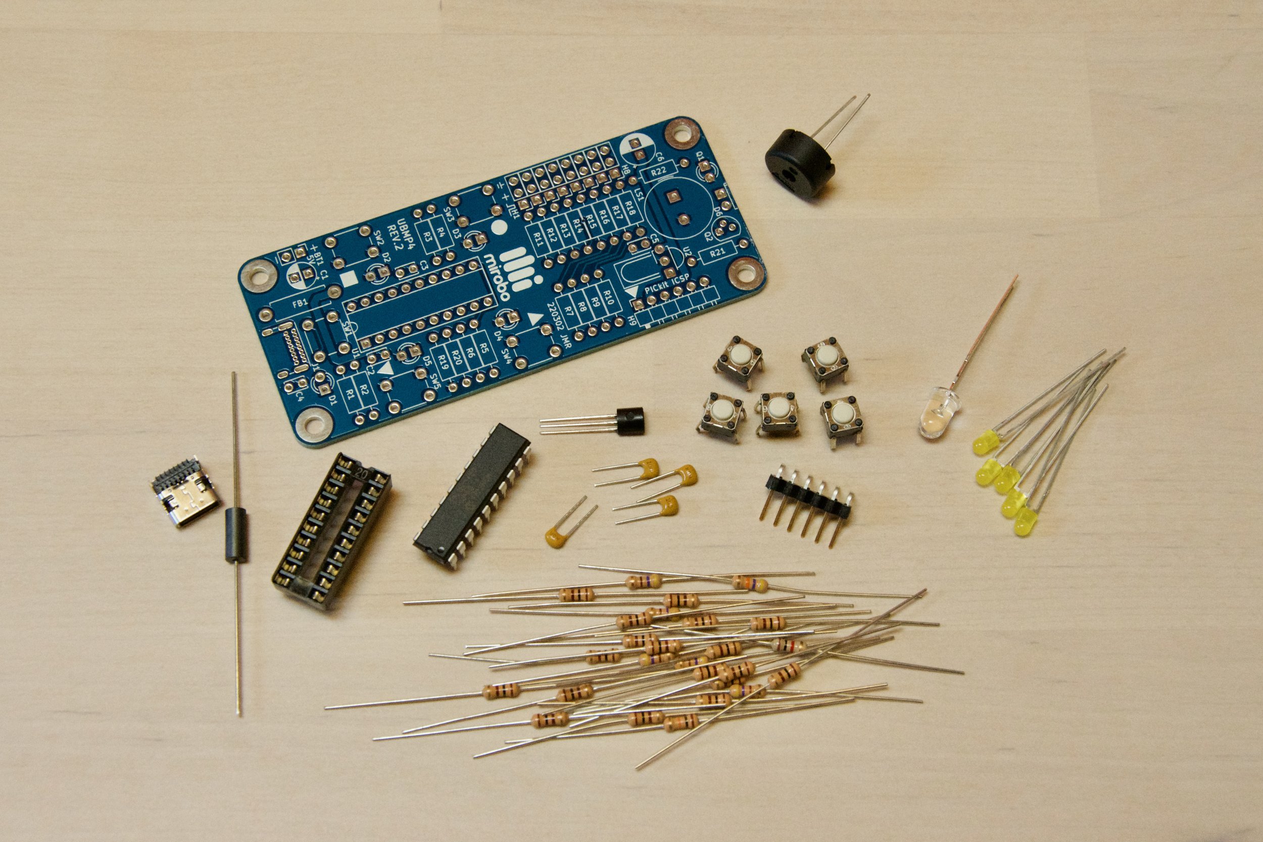
Step 1 - Check your components
First, confirm that you have all of the required and optional components in your kit.
If you are starting with a bare UBMP4 board instead of a kit and need to obtain the components first, download the more detailed UBMP4 Parts List (.csv) or purchase parts from this shared Digital-Key parts list.
Required components
1 - UBMP4.2 or UBMP4.3 printed circuit board
14 - 100Ω, 1/4W resistors (colour code: brown, black, brown, gold)
5 - 470Ω, 1/4W resistors (colour code: yellow, violet, brown, gold)
2 - 1.0kΩ, 1/4W resistors (colour code: brown, black, red, gold)
1 - 4.7kΩ, 1/4W resistor (colour code: yellow, violet, red, gold)
2 - 5.1kΩ 1%, 1/4W resistors (UBMP4.3 only, colour code: green brown black brown brown)
1 - USB-C connector
5 - 6mm pushbuttons
1 - 20-pin DIP socket
1 - ferrite inductor (un-marked black cylinder)
1 - 1µF ceramic monolithic capacitor (numeric code: 105)
2 - 100nF ceramic monolithic capacitor (numeric code: 104)
1 - 470nF ceramic monolithic capacitor (numeric code: 474)
1 - 12mm piezo beeper (non-polarized)
5 - 3mm LEDs
1- PIC16F1459-I/P microcontroller
Optional components
The optional components are supplied with the kit but are not required to complete the UBMP4 introductory activities. See the configurations section, below, to determine which optional components to install.
1 - 6-pin right-angle header strip
1 - 2N3904 NPN transistor
1 - 3mm phototransistor (opaque black case)
1 - 3mm ambient light sensor (transparent case)
1 - 5mm IR LED
1 - TSOP38238 IR demodulator
Omitted components
The following components are not supplied as part of the UBMP4 kit, but may be provided and installed by the user based on their anticipated use of UBMP4.
8 - 3-pin header pin or socket strips for H1-H8 (depending on user preference)
C6 - 47µF electrolytic capacitor (recommended when driving servos on any header pins)
C4 - 10nF ceramic monolithic capacitor (not typically necessary, but included on the PCB as per the USB specifications)
Step 2 - Choose your UBMP4 configuration
UBMP4 can be built in a number of different configurations. Refer to the schematic diagram and identify the components labelled as optional (in the dashed boxes). Optional components are not used in any of the introductory activities on this site. Leaving the optional components uninstalled or installing them later has a number of advantages, especially for educational users. Three common configurations are described, below:
Important assembly considerations
Before soldering your UBMP4, there are some important points you need to consider:
UBMP4 can be assembled with or without a number of optional components – before beginning assembly, check the schematic diagram to explore the configurations and to determine which optional components you will install.
Soldering the USB-C connector is challenging due to its tiny, closely-spaced pins. The simplest method involves dragging solder across the pins using a wide blade soldering iron tip, although individually soldering each pin with a fine conical point soldering iron tip is also possible.
D6 and Q1, the infrared LED and phototransistor/ambient light sensor, respectively, can be installed facing perpendicular to, or parallel to the printed circuit board. Determine the best orientation for your intended application before installing them.
IR demodulator, U2, is designed to be installed flat on the printed circuit board. It is easiest to pre-bend its pins 90° before installation in the circuit board.
Education Starter
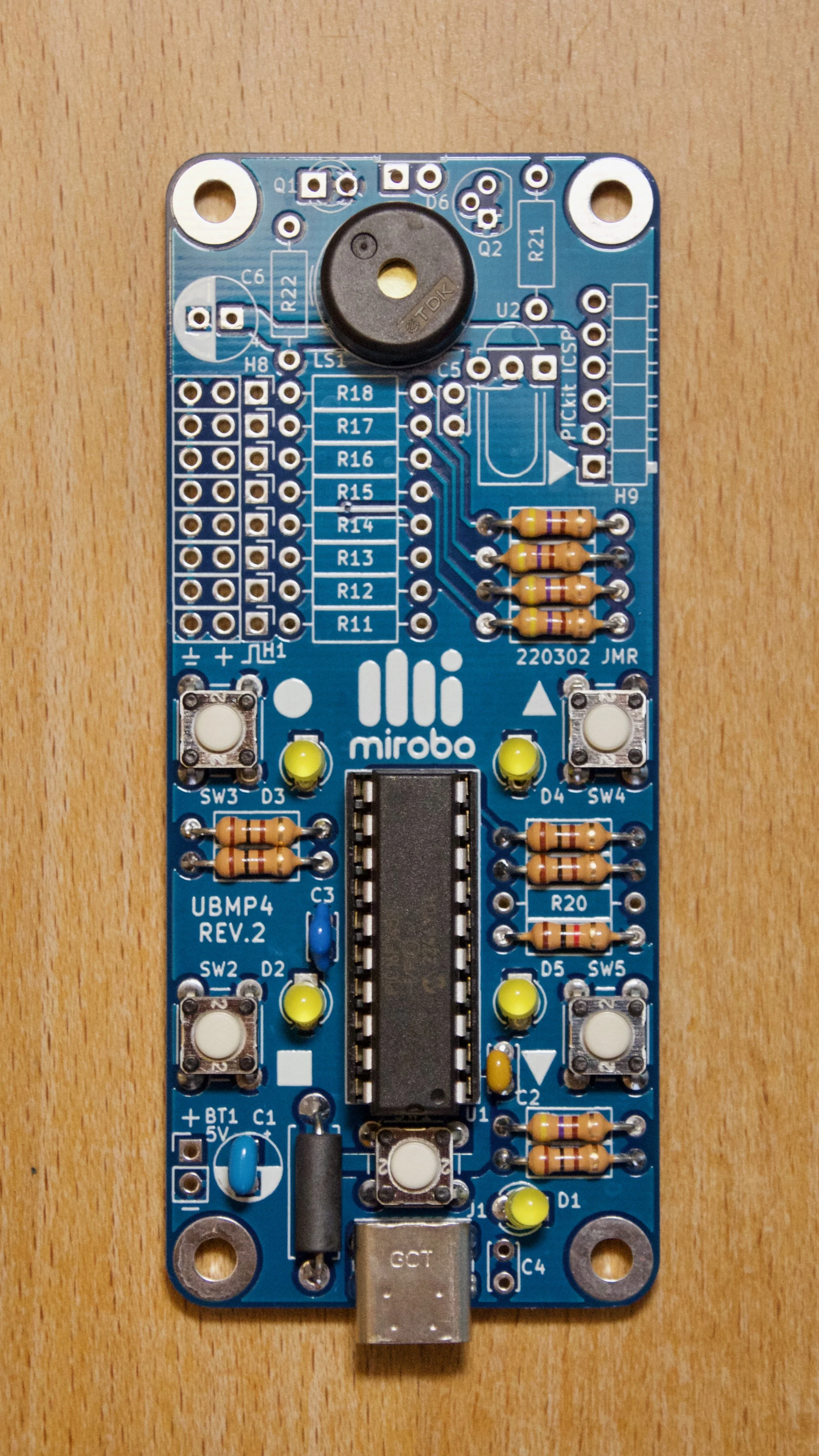
The Education Starter configuration is recommended for first-time computer technology learners in schools. In this version, none of the optional components are added (although adding the expansion header resistors can make debugging easier). This minimal configuration allows students to build UBMP4 and start learning to program quickly, saves costs for un-used components, and allows for student customization based on project choice later.
Starter configuration
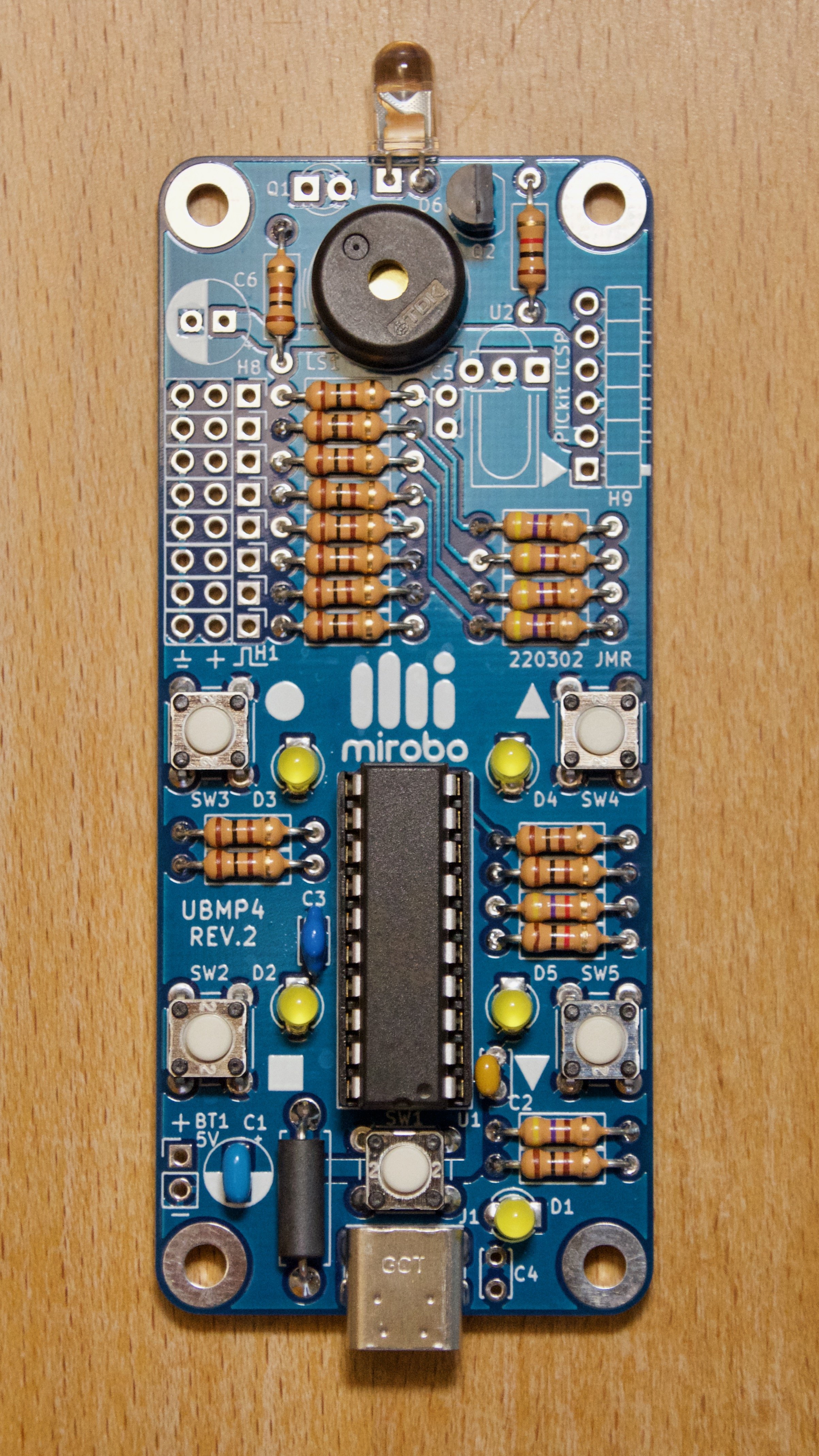
The Starter configuration is for hobbyist users looking to get started with PICmicro programming and interfacing. This is the recommended configuration if the final application of for UBMP4 isn’t yet known. The Starter configuration is similar to the Education Starter configuration in that a number of components are intentionally omitted. Doing this provides some advantages for new learners, and does not impact the final application as they can easily be added later.
Complete build
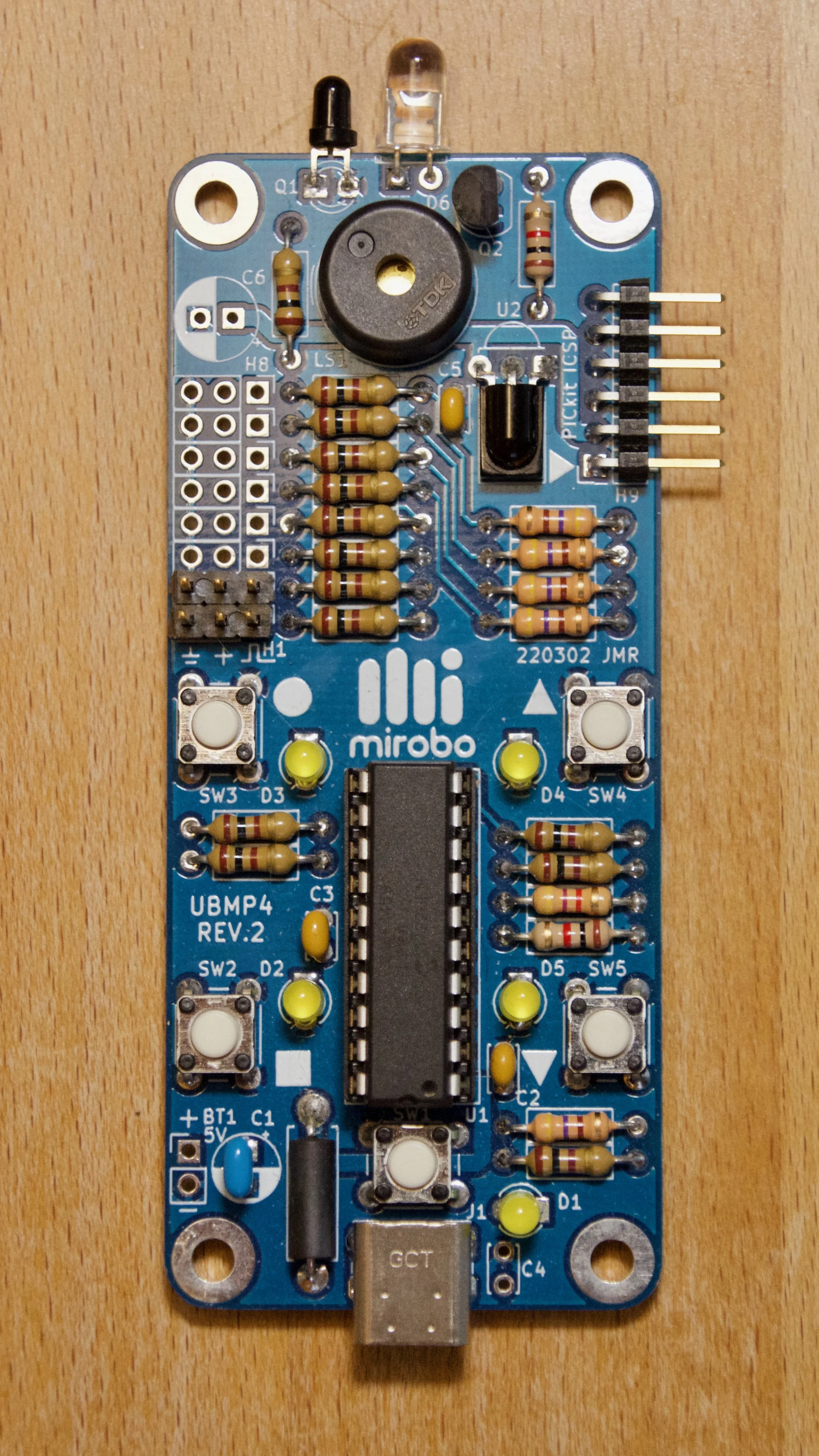
The Complete build provides the most versatility for advanced users and includes all of the components a user decides they need. Pre-assembled UBMP4 circuits are shipped in the completely built configuration, with an ambient light sensor installed vertically, and IR LED D6 installed in parallel with the plane of the printed circuit board for remote-control applications. This example has an IR phototransistor installed beside D6 instead of the ambient light sensor as well as added header pins for H1 and H2.
Step 3 - Component installation
Components are installed in order of smallest to tallest to make building the circuit easier. Component orientation is not critical for the resistors, pushbuttons, ceramic monolithic capacitors, ferrite, or piezo beeper. Orientation is important for polarized capacitors, LEDs, and optical sensing components – follow the instructions in the assembly steps below.
USB-C socket J1 is difficult to install. The easiest method of soldering it into place is by drag soldering its contacts with a flat/blade soldering iron tip after the resistors have been installed. Watch the video to see a demonstration of the drag soldering process. Or, alternatively, it can be soldered with a very steady hand and a needle-point conical soldering iron tip.
Education Starter
Install the 100Ω resistors R1, and R3-R6. Optionally install R11-R18 if the expansion header will be used for debugging or interfacing.
Install 470Ω resistors R2 and R7-R10.
Install 1.0kΩ resistor R19.
Install 5.1kΩ resistors R23-R24 (UBMP4 revision 3 only).
Install USB-C socket J1 by drag soldering.
Install pushbuttons SW1-SW5.
Install 20-pin DIP socket U1, ensuring the notch matches the location of the painted notch on the circuit board silkscreen (closest to the USB-C port). Solder one pin on each side of the chip socket, ensure the socket is properly seated, and then finish soldering the remaining pins.
Install ferrite F1 – it looks like a resistor, but is dark in colour and has no markings.
Install 1µF capacitor C1.
Install 100nF capacitor C2.
Install 470nF capacitor C3.
Install piezo beeper LS1.
Install 3mm LEDs D1-D6. LEDs are polarized and have one long and one short lead. The LED solder pads on the circuit board are different shapes – one is circular and the other one is square. Install the long lead of each LED into the square pad, and the short lead into the round pad. To ensure the LEDs are installed straight, solder one lead of the LED first, then check and re-heat and adjust the LED if necessary before soldering the second lead.
Starter Configuration
Install the 100Ω resistors R1, R3-R6, R11-R18, and R22.
Install 470Ω resistors R2 and R7-R10.
Install 1.0kΩ resistors R19 and R21.
Install 4.7kΩ resistor R20.
Install 5.1kΩ resistors R23-R24 (UBMP4 revision 3 only).
Install USB-C socket J1 by drag soldering.
Install pushbuttons SW1-SW5.
Install 20-pin DIP socket U1, ensuring the notch matches the location of the painted notch on the circuit board silkscreen (closest to the USB-C port). Solder one pin on each side of the chip socket, ensure the socket is properly seated, and then finish soldering the remaining pins.
Install ferrite F1 – it looks like a resistor, but is dark in colour and has no markings.
Install 1µF capacitor C1.
Install 100nF capacitor C2.
Install 470nF capacitor C3.
Install piezo beeper LS1.
Install 3mm LEDs D1-D6. LEDs are polarized and have one long and one short lead. The LED solder pads on the circuit board are different shapes – one is circular and the other one is square. Install the long lead of each LED into the square pad, and the short lead into the round pad. To ensure the LEDs are installed straight, solder one lead of the LED first, then check and re-heat and adjust the LED if necessary before soldering the second lead.
Optionally, install 6-pin header H9. H9 is used for programming UBMP4 using Microchip’s PICkit-4 or PICkit-5 in-circuit programmers. H9 is not needed for bootloader programming, but adding H9 allows the PIC16F1459 to be programmed in-circuit without using a bootloader.
Solder the shorter, bent silver contact of the header into the circuit board, so its plastic frame lays flat on the board, and leave the longer, straight gold contacts exposed and sticking out over the edge of the printed circuit board.Optionally, install NPN transistor Q2 if the IR LED D6 will be used for remote control applications or if the LED will be used with phototransistor Q1 for IR sensing applications. Ensure its orientation matches the silkscreen outline on the printed circuit board.
Optionally, install IR LED D6. D6 is used for transmitting IR remote control codes and as a light source for phototransistor Q1 in object sensing applications. Determine the best mounting orientation for D6 before soldering it into UBMP4.
D6 can be mounted either upright, or parallel with the circuit board (with its leads bent 90°, which is best when it is used for TV remote control applications). Install the long lead of the LED into the square pad, and the short lead into the round pad on the printed circuit board.Optionally, install optical sensor Q1. Q1 can be either an ambient light sensor (in a transparent case, used for measuring visible light intensity), or a phototransistor (in a black filtered case, optimized for responding to infrared light).
Determine best the mounting orientation for Q1 – either upright, or parallel to the circuit board. The long lead is the emitter, the short lead is the collector.
On UBMP4.3, install Q1 with its long lead into the square pad as was done with the LEDs (this was done for consistency with the LEDs in classroom settings, and you can also refer to the symbols printed on the bottom of the circuit board for reference).
On UBMP4.2, install the long lead of the optical sensor into the round pad, and the short lead into the square pad on the printed circuit board (opposite to how the LEDs are installed).Optionally, install IR demodulator U2 and 100nF capacitor C5. The IR demodulator is used only to receive IR signals from a TV remote control or another UBMP4 acting as a remote transmitter. Bend the leads at 90° and mount U2 with its flat side against the printed circuit board, with its cylindrical ‘window’ facing up, away from the circuit board.
Complete Build
Install the 100Ω resistors R1, R3-R6, R11-R18, and R22.
Install 470Ω resistors R2 and R7-R10.
Install 1.0kΩ resistors R19 and R21.
Install 4.7kΩ resistor R20.
Install 5.1kΩ resistors R23-R24 (UBMP4 revision 3 only).
Install USB-C socket J1 by drag soldering.
Install pushbuttons SW1-SW5.
Install 20-pin DIP socket U1, ensuring the notch matches the location of the painted notch on the circuit board silkscreen (closest to the USB-C port). Solder one pin on each side of the chip socket, ensure the socket is properly seated, and then finish soldering the remaining pins.
Install ferrite F1 – it looks like a resistor, but is dark in colour and has no markings.
Install 1µF capacitor C1.
Install 100nF capacitor C2.
Install 470nF capacitor C3.
Install piezo beeper LS1.
Install 3mm LEDs D1-D6. LEDs are polarized and have one long and one short lead. The LED solder pads on the circuit board are different shapes – one is circular and the other one is square. Install the long lead of each LED into the square pad, and the short lead into the round pad. To ensure the LEDs are installed straight, solder one lead of the LED first, then check and re-heat and adjust the LED if necessary before soldering the second lead.
Optionally, install 6-pin header H9. H9 is used for programming UBMP4 using Microchip’s PICkit-4 or PICkit-5 in-circuit programmers. H9 is not needed for bootloader programming, but adding H9 allows the PIC16F1459 to be programmed in-circuit without using a bootloader.
Solder the shorter, silver contact of the header into the circuit board, with the plastic frame laying flat on the board, and leave the longer, gold contacts exposed over the edge of the printed circuit board.Install NPN transistor Q2. Ensure its orientation matches the silkscreen outline on the printed circuit board.
Install IR LED D6. D6 is used for transmitting IR remote control codes and as a light source for phototransistor Q1 in object sensing applications. Determine the best mounting orientation for D6 before soldering it into UBMP4.
D6 can be mounted either upright, or parallel with the circuit board (with its leads bent 90°, which is best when it is used for TV remote control applications). Install the long lead of the LED into the square pad, and the short lead into the round pad on the printed circuit board.Optionally, install optical sensor Q1. Q1 can be either an ambient light sensor (in a transparent case, used for measuring visible light intensity), or a phototransistor (in a black filtered case, optimized for responding to infrared light).
Determine best the mounting orientation for Q1 – either upright, or parallel to the circuit board. The long lead is the emitter, the short lead is the collector.
On UBMP4.3, install Q1 with its long lead into the square pad as was done with the LEDs (this was done for consistency with the LEDs in classroom settings, and you can also refer to the symbols printed on the bottom of the circuit board for reference).
On UBMP4.2, install the long lead of the optical sensor into the round pad, and the short lead into the square pad on the printed circuit board (opposite to how the LEDs are installed).Install IR demodulator U2 and 100nF capacitor C5. The IR demodulator is used only to receive IR signals from a TV remote control or another UBMP4 acting as a remote transmitter. Bend the leads at 90° and mount U2 with its flat side against the printed circuit board, with its cylindrical ‘window’ facing up, away from the circuit board.
Step 4 - Final steps and testing
Inspect the solder connections and ensure there are no short circuits. Trim the component leads short to minimize the possibility that any adjacent pins will touch. Clean the circuit board with your solder’s recommended flux remover to remove any flux residue (unless you used a no-clean flux). Thoroughly dry the circuit board and re-inspect all solder connections.
Set a multimeter to its resistance range and measure the resistance across the BT1 terminals (connect red to + and black to - ) to check for a power supply short circuit. A resistance in the kilo-Ohms range is high enough to ensure there is not a short circuit between the power and ground paths. If there is a very low resistance across the BT1 terminals, your circuit board may have solder bridging the power and ground circuits. Carefully check the solder connections again, and remove any solder blobs that bridge component leads or expand beyond their individual pads.
Align the pre-programmed PIC16F1459-I/P microcontroller so that its notch matches the notch on the chip socket (it should be facing the USB-C connector). Ensure each of the pins is engaged in between the contacts of the chip socket and then firmly press the microcontroller into the chip socket.
Connect the circuit board to your computer’s USB port using a USB-A to USB-C cable or USB-C to USB-C cable (UBP4.2 may not respond when connected with a USB-C to USB-C cable). After connection, LED D1 should light to indicate the microcontroller is operating. Press and release pushbutton SW1 to start the bootloader and verify that a device named PIC16F1459 appears in your computer’s file browser.
That’s it! Your UBMP4 is now ready to be programmed. Follow the instructions in one of the programming activities on the UBMP4 page to create your first program.
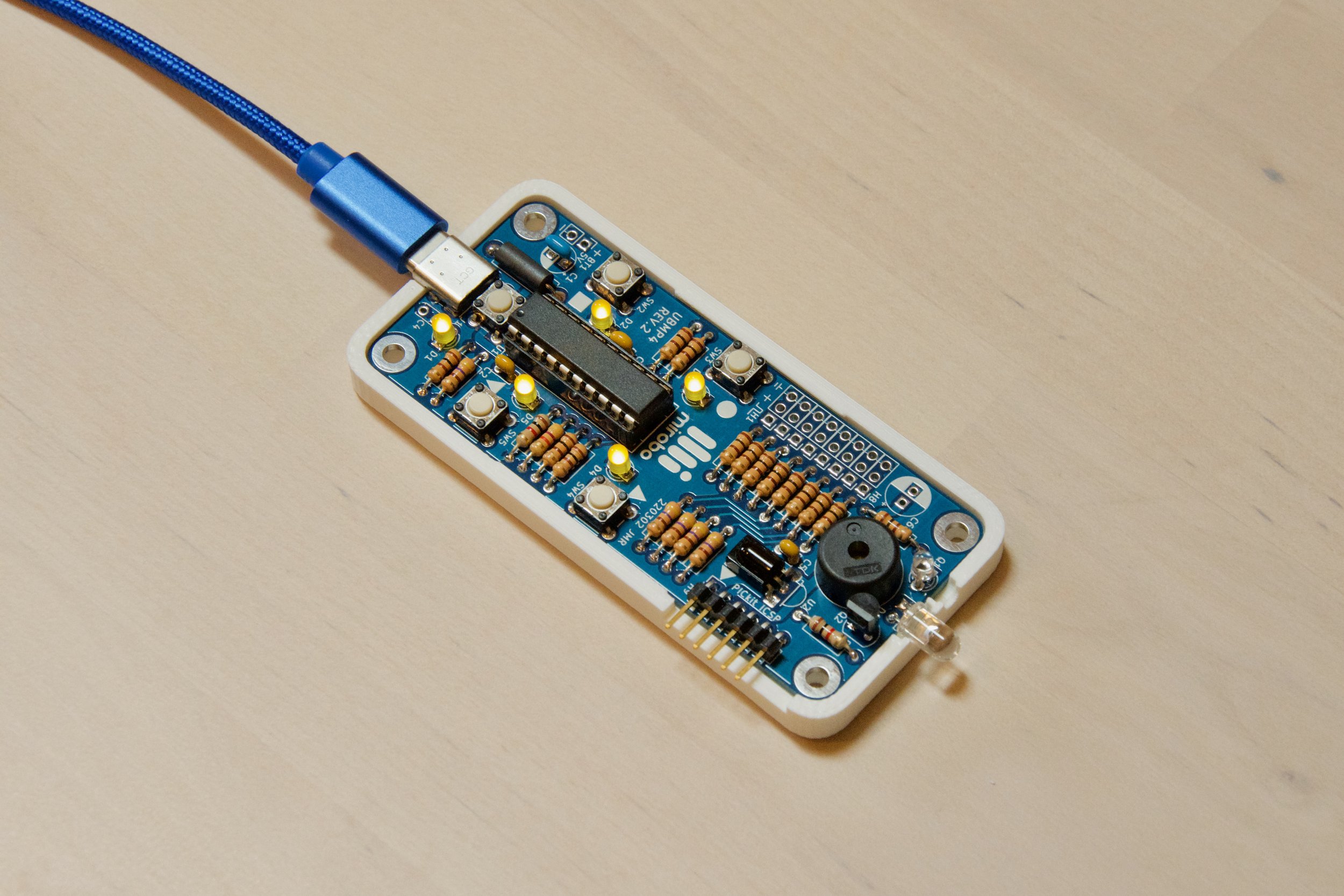
Do you have access to a 3D printer? Download the .STL file to print a protective UBMP4 bottom cover as seen on this complete UBMP4.2 build.